Integrated Air Intake System

a technology of air intake system and integrated air, which is applied in the direction of roofs, combustion air/fuel air treatment, machines/engines, etc., can solve the problems of obstructing visibility of work vehicles by work vehicles, inconvenience, and only intensifying disadvantages

Inactive Publication Date: 2010-12-02
DEERE & CO
View PDF96 Cites 18 Cited by
  • Summary
  • Abstract
  • Description
  • Claims
  • Application Information

AI Technical Summary

Benefits of technology

[0007]The invention overcomes each of the above disadvantages by providing an air intake system integral to and formed by a hood of an engine enclosure as well as other conventional components within the engine enclosure. The engine enclosure is formed by at least the hood, two sidewalls, a grille and a screen. An insulated air duct forms an integral part of the hood and is in communication with a filter for engine air intake. The air entering the air duct may be moved into the engine enclosure via a fan for the purpose of moving air from the ambient surroundings outside of the vehicle to a location inside the vehicle and, typically, through a heat exchanger. The air may also be pre-cleaned by a screen as well as relative movement between debris and air prior to and after pre-cleaning of the air by the screen. The entrance to the air duct is preferably located such that the ambient air entering the air channel tends toward ambient temperature, i.e., air that has not been preheated via passage through the heat exchanger. Thus, a preferable location for the entrance to the air duct is, horizontally, between the screen and the heat exchanger and, vertically, toward the top of the screen and the heat exchanger. Further, the entrance passage is preferably substantially orthogonal to the axis of the fan or at an angle greater than 90 degrees to the axis of the fan or the flow direction of the air. Such an arrangement gives the air a chance for a first pre-cleaning via the screen as well as a second pre-cleaning via the general inability of debris to change direction and move upwards and into the entrance passage to the same extent as air.

Problems solved by technology

As previously indicated, conventional above-hood air intake systems for work vehicles tend to obstruct visibility for the work vehicle operator.
These disadvantages are only intensified by the relatively large pre-cleaners that are often attached to the entry point of such systems in high debris environments.
A major disadvantage of many conventional under hood air intake systems where the intake port is located in the engine compartment is that they tend to intake preheated air via convection and radiation with respect to the engine.
Other under hood air intake designs tend to avoid this problem but all under hood designs tend to use only screens and filters to remove debris as the use of pre-cleaners under the hood tends to: (1) take up too much precious space, i.e., premium space; and (2) the inconvenience caused by the debris typically ejected by such devices.

Method used


Image

  • Integrated Air Intake System
  • Integrated Air Intake System
  • Integrated Air Intake System

Examples


Embodiment Construction

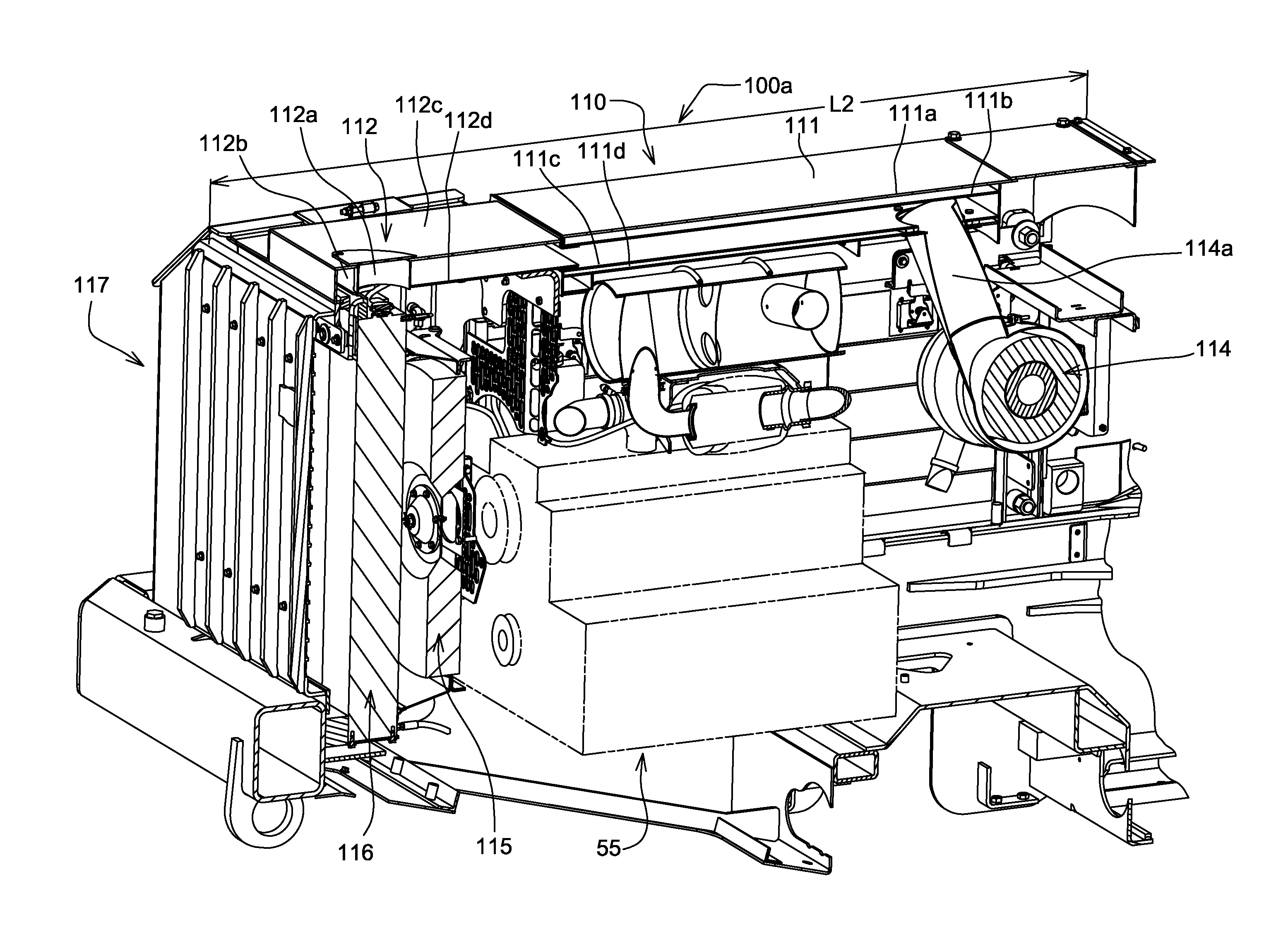
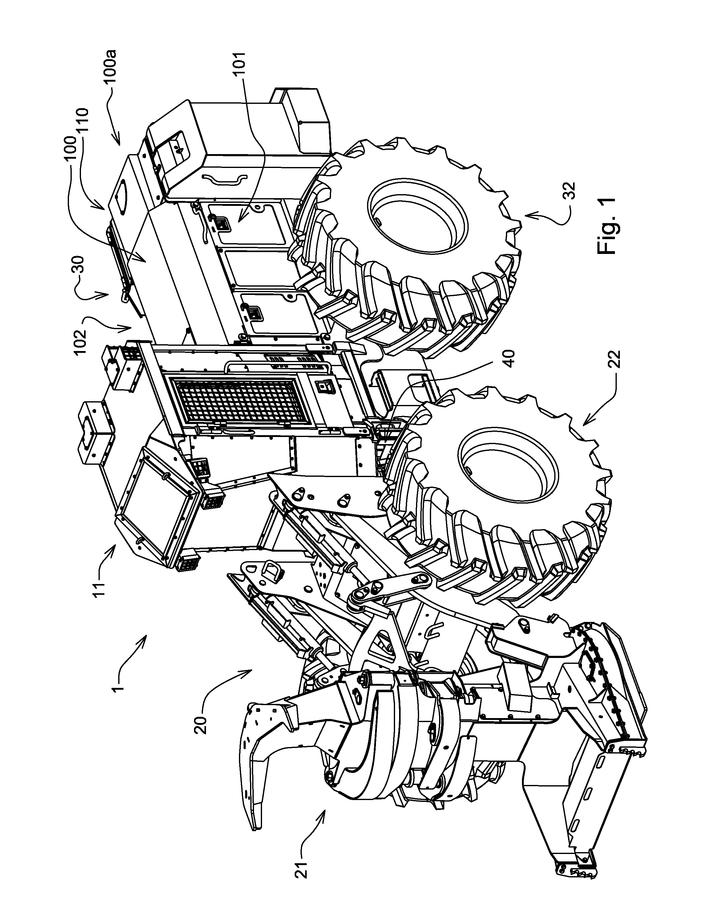
[0019]FIG. 1 illustrates an exemplary embodiment of a work vehicle in which the invention is used. The particular work vehicle illustrated in FIG. 1 is a wheeled feller buncher 1; an articulated vehicle having a front body portion 20 connected to a rear body portion 30 via pivots 40, the wheeled feller buncher 1 being steered by pivoting of the front body portion 20 relative to the rear body portion 30 in a manner well known in the art. The rear body portion 30 includes an engine enclosure 100 having a first sidewall 101, a second sidewall 102 and a hood 100a with an integrated air intake duct 110 and a supporting structure 113 (FIG. 5).

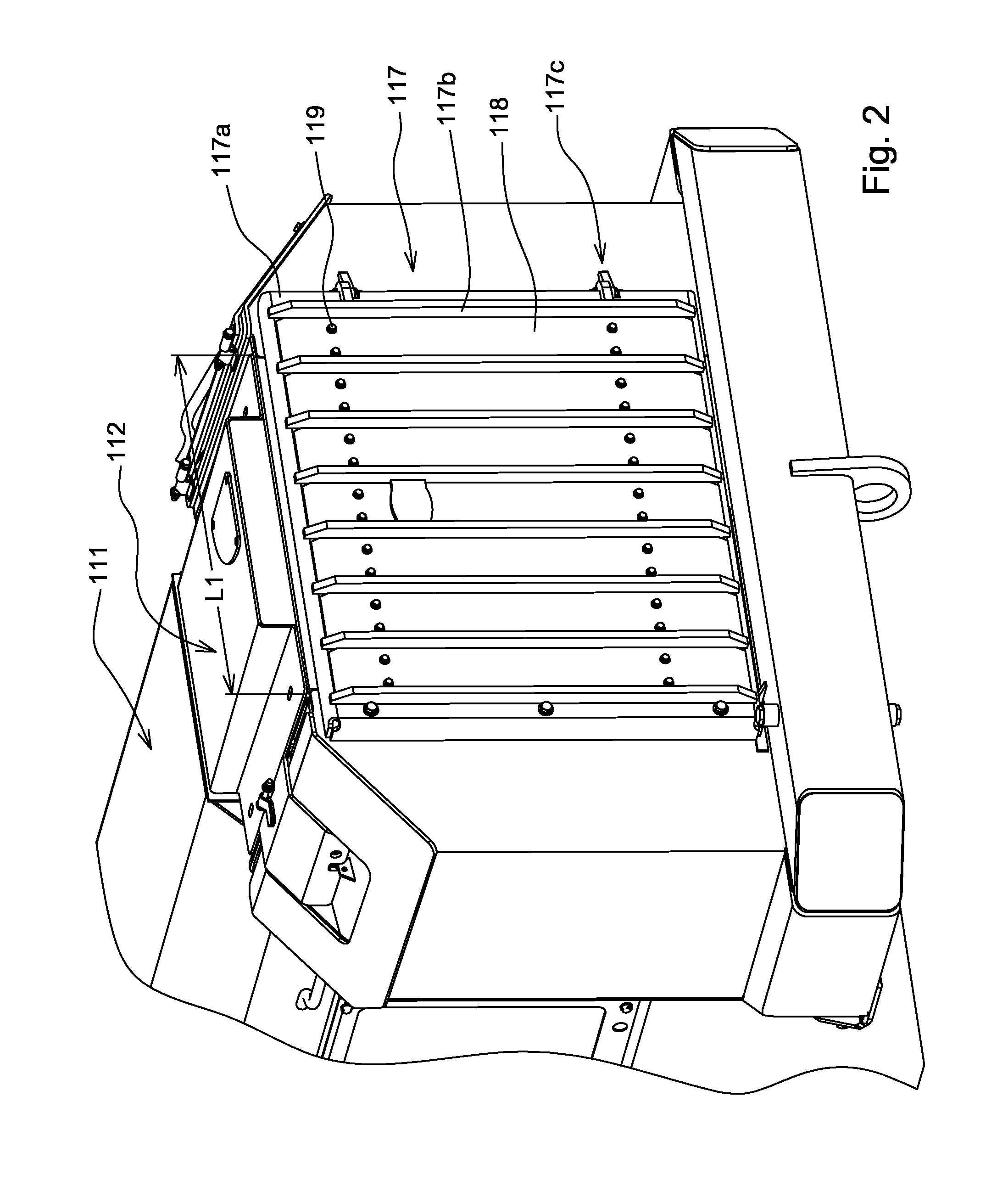
[0020]FIGS. 2 and 3 illustrate that, in this exemplary embodiment, a grille screen 117 forms a portion of the engine enclosure 100. As shown in FIGS. 5 and 6, in this particular embodiment, the grille screen 117 includes a grille bar support 117a, a plurality of grille bars 117b and a screen 118 with a multiplicity of holes, each having an approximat...


PUM


Abstract

An engine air intake system is provided which is formed by an engine compartment. A fan and a grille screen are used to remove a portion of debris from air external to the vehicle. After the air is partially cleaned via the grille screen, it moves toward a heat exchanger carrying a portion of the remaining debris with it. A portion of the debris may fall out of the air via gravitational effects. A portion of the air then moves up and into an entrance passage for an air intake duct that is integrated with the hood of the engine enclosure, this portion having been further cleaned via debris passage to and through the heat exchanger as well as gravitational effects. The air then travels through the air intake duct and passes through an air filter where a portion of the remaining debris is removed prior to the air being supplied to the engine intake.

Description

CROSS REFERENCE TO RELATED APPLICATIONS[0001]This is a non-provisional application based upon U.S. provisional patent application Ser. No. 61 / 182,420, entitled “INTEGRATED AIR INTAKE SYSTEM”, filed May 29, 2009.FIELD OF THE INVENTION[0002]The invention relates to the structure and operation of air intake systems and methods of supplying intake air to internal combustion engines. More specifically, it relates to a method, system and structure for supplying ambient or non-preheated air to an internal combustion engine for a work vehicle or mobile construction machine such as, for example, a wheeled feller buncher.BACKGROUND OF THE INVENTION[0003]Most mobile construction machines employ above-hood engine air intakes. The above-hood air intake is usually covered by a shield to prevent the entrance of rain and other precipitation. Above-hood air intakes are typically designed to be low-profile, i.e., have as small of a visual signature as possible. However, these intakes are required to ...

Claims


Application Information

Patent Timeline
Patent Type & Authority Applications(United States)
IPC IPC(8): B60R99/00
CPCF02M35/164
Inventor HINSHAW, ERIC J.BRAUN, KEVIN G.
Owner DEERE & CO
Why Eureka
Try Eureka