Winding body for an electric motor and method for producing a winding body for an electric motor

a technology of electric motors and winding bodies, which is applied in the direction of windings, mechanical energy handling, dynamo-electric components, etc., can solve the problems of unjustifiable amount of automation and complicated handling, and achieve the effects of reducing efficiency, increasing output of drives, and increasing efficiency of drives

Active Publication Date: 2010-12-02
ROBERT BOSCH GMBH
View PDF13 Cites 4 Cited by
  • Summary
  • Abstract
  • Description
  • Claims
  • Application Information

AI Technical Summary

Benefits of technology

[0016]Known electric motors comprising an air-gap winding are incapable of being automated due to the presence of the winding body, and are therefore unusable in series production. Due to advancements made in rechargeable-battery technology, power tools that are powered using rechargeable batteries are becoming more significant than mains-operated devices. Substantially more applications are being covered using rechargeable-battery operated products, and the output of the drives is increasing; the efficiency of the drive is becoming more significant, and the limits of the conventional DC motor using permanent-magnet excitation are being reached in many applications. Examples of products that are affected include screwdrivers, drills, impact drills, and rotary hammers, each of which is in the top performance class. By comparison, angle grinders and circular saws are even higher in terms of performance requirements. Disadvantages of the DC motor using permanent-motor excitation are, e.g., that the rotational speed is limited in terms of the requirements of the application. The reasons are, inter alia, due to the commutation and the risk of demagnetization taking place when the motor is started up. The working point is usually located in the range of markedly reduced efficiency. The heat losses from the armature are difficult to dissipate. Dissipation heat that occurs on the commutation device results in decreases in reliability. Product-specific mechanical reactions influence the commutation and result in a reduced service life.
[0017]In contrast, the electric motor that is provided allows the rotational speed to be increased to twice that of a DC motor having the same output. The power density of existing applications may be doubled, or a motor having half as much volume is required for the same output. The weight may be reduced accordingly. Any additional electronics that are required may be installed at a different point that does not affect the overall volume of the device. The efficiency may be held at a high level across nearly the entire relevant working range, and, at the optimum, is greater than it is with a comparable DC motor. Due to the good efficiency, less dissipation heat is produced that would have to be released. Although the performance requirements are higher, it is possible to avoid problems related to service life and reliability since the electric motor and, therefore, the power tool are particularly robust and reliable, and they have a long service life. The influence of effects that are dependent on operating temperature, and product-specific mechanical reactions to the functionality of the power tool are advantageously diminished.
[0018]A power tool is provided, in particular a power tool that includes an insertion tool that is driveable in a percussive and / or rotary manner, and that includes an electric motor comprising an air-gap winding, in particular an electronically commutating electric motor, in the case of which a winding body is located in an air gap between a stator iron core and a rotor. Due to the high rotational speeds that are attainable due the design, and due to the low inductance that is attainable due to the design, the high quality electric motor has properties that are superior to those of other electric motors such as BLDC motors that include a slotted stator, or DC motors that use permanent-magnet excitation. The preferred power tool is correspondingly robust and reliable.

Problems solved by technology

Three separate litz wires are used to manufacture a three-phase, two-pole winding, thereby greatly complicating handling which would require an unjustifiable amount of effort to automate.

Method used


Image

  • Winding body for an electric motor and method for producing a winding body for an electric motor
  • Winding body for an electric motor and method for producing a winding body for an electric motor
  • Winding body for an electric motor and method for producing a winding body for an electric motor

Examples


Embodiment Construction

[0028]Elements that are the same or similar-acting are labelled using the same reference numerals in the figures.

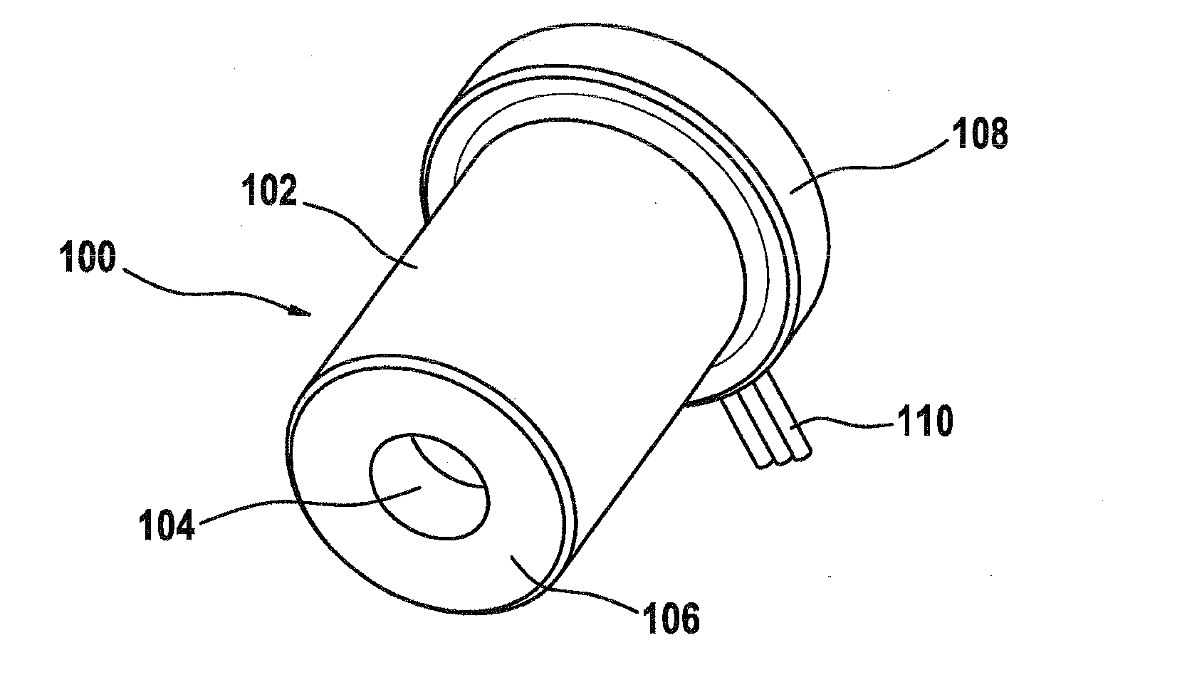
[0029]FIG. 1 shows a preferred winding body 100 for an electric motor, which is designed, e.g., as an electronically commutating, brushless direct current electric motor (BLDC motor) that includes an air-gap winding. The winding body is coreless in design and is shaped roughly as a pot having a cylindrical section 102, an inwardly pointing winding overhang 106 on one end which forms a base which is open in the center, and an outwardly folded winding overhang 108 which forms a ridge-like edge on the other end of winding body 100. Current may be supplied to the winding body during operation via an electrical contact 110. In the installed state, a rotor of the electric motor is located in interior 104 of winding body 100; the rotor shaft of the rotor extends out of both ends of winding body 100.

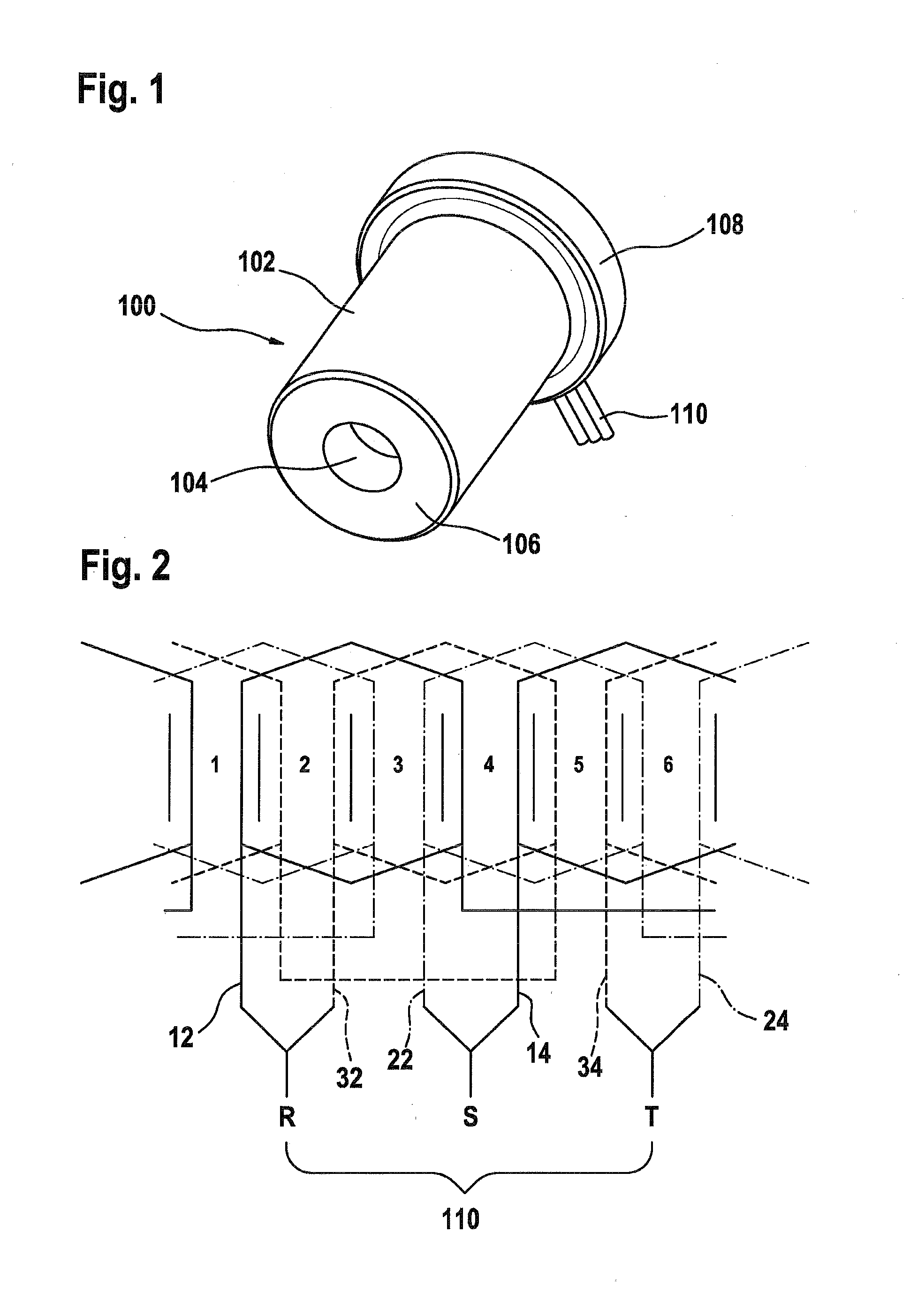
[0030]FIG. 2 shows a winding scheme of the type used for a three-phase, two-pole ...


PUM


Abstract

The invention relates to a winding body for an electric motor and, in particular a brushless direct current electric motor (200) with an air gap winding. At least two bobbins (12, 14; 22, 24; 32, 34) per stand (10, 20, 30) are provided. The invention also relates to a method for the production of said winding body. According to the invention, the bobbins (12, 14; 22, 24; 32, 34) of a strand (10; 20; 30) of the winding body (100) are wound immediately behind each other.

Description

BACKGROUND INFORMATION[0001]The present invention relates to a winding body for an electric motor and a method for producing a winding body for an electric motor according to the preambles of the independent claims.[0002]Brushless direct current motors (BLDC motors) comprising an air-gap winding and coreless winding bodies are known. Typically, the winding for a winding body of this type is first placed on a mandrel which holds the coils in position during the winding process. Next, the winding, which is typically composed of stoved-enamel wire, is brought into its final shape via heating and pressing; the winding body retains this final shape after it is heated. Finally, the winding body is removed from the mandrel, and it may be further processed.[0003]Three separate litz wires are used to manufacture a three-phase, two-pole winding, thereby greatly complicating handling which would require an unjustifiable amount of effort to automate. The winding bodies of BLDC motors of this ty...

Claims


Application Information

Patent Timeline
Patent Type & Authority Applications(United States)
IPC IPC(8): H02K3/28H02K7/14
CPCH02K3/47
Inventor SCHULZ, MARTINRINDSBACHER, HANSRIEKER, WERNEROBERLI, GERHARDZSCHOCKE, ANDRE
Owner ROBERT BOSCH GMBH
Why Eureka
Try Eureka