Eureka AIR delivers breakthrough ideas for toughest innovation challenges, trusted by R&D personnel around the world.

Methods, systems and apparatus for controlling operation of two alternating current (AC) machines

Inactive Publication Date: 2010-12-02
GM GLOBAL TECH OPERATIONS LLC
View PDF6 Cites 10 Cited by
  • Summary
  • Abstract
  • Description
  • Claims
  • Application Information

AI Technical Summary

Benefits of technology

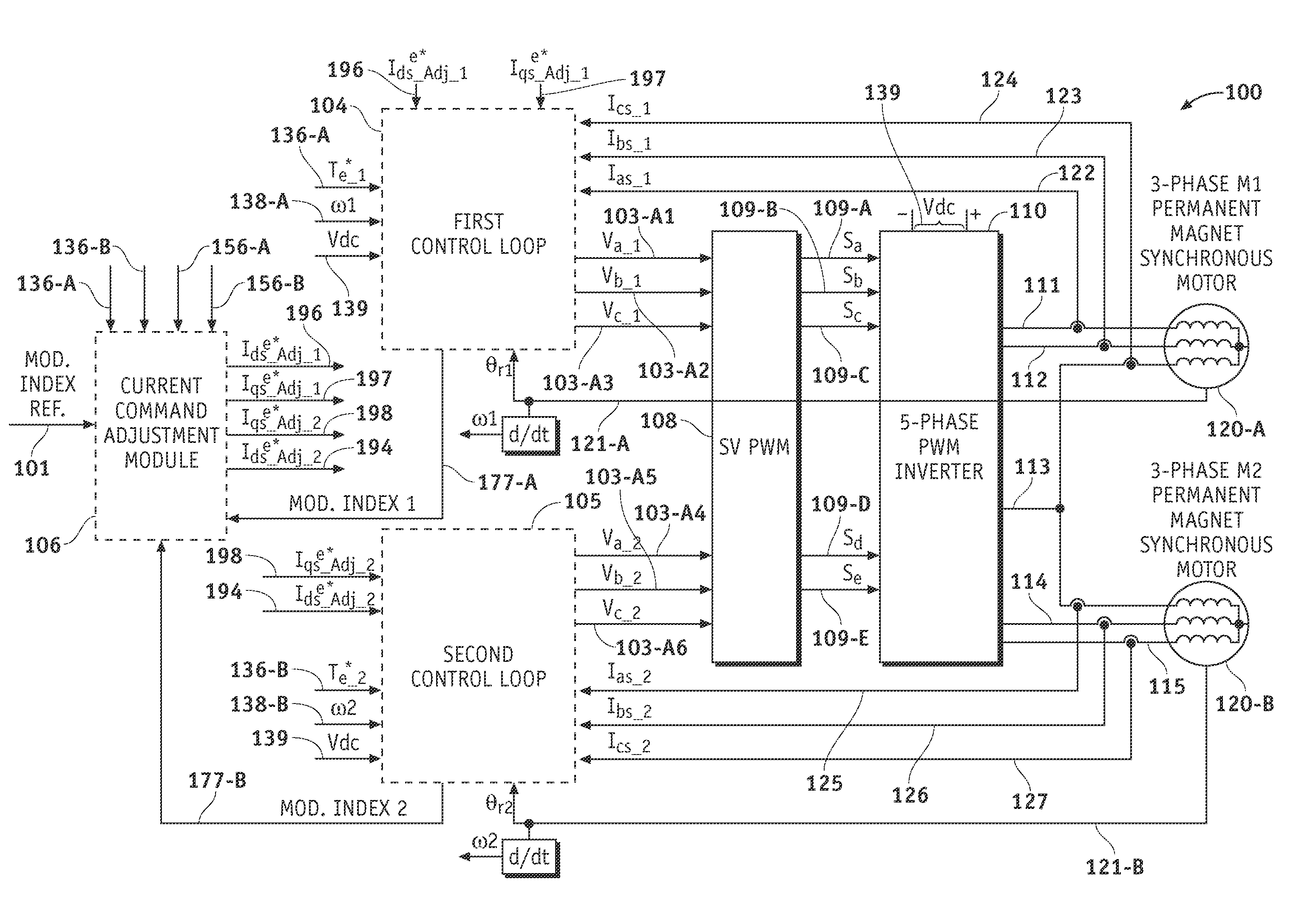
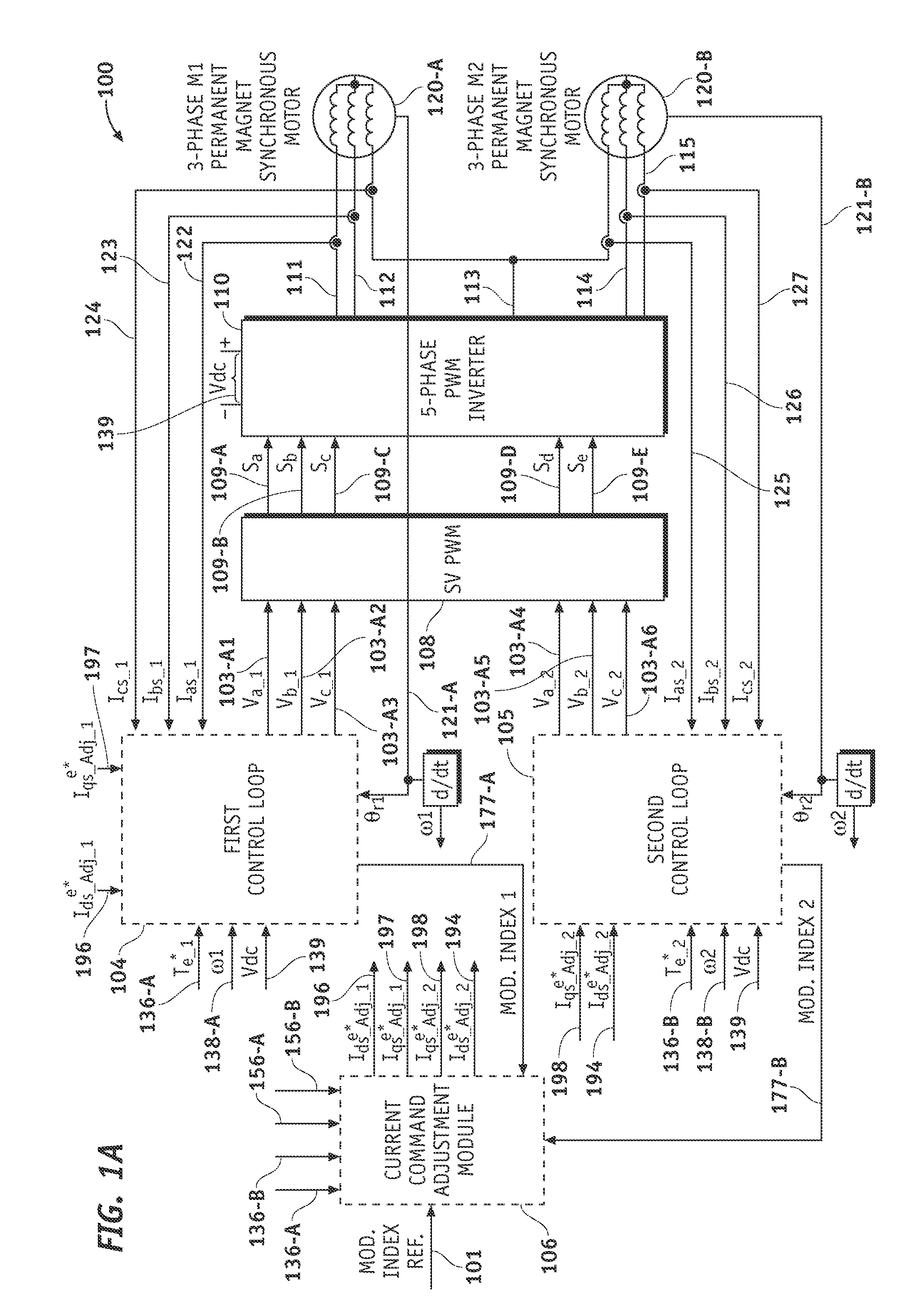
[0008]In accordance with one embodiment, a system is provided for controlling two alternating current (AC) machines. The system comprises a DC input voltage source that provides a DC input voltage, a voltage boost command control module (VBCCM), a five-phase PWM inverter module coupled to the two AC machines, and a boost converter coupled to the inverter module and the DC input voltage source. The boost converter is designed to supply a new DC input voltage to the inverter module having a value that is greater than or equal to a value of the DC input voltage. The VBCCM generates a boost command signal that controls the boost converter such that the boost converter generates the new DC input voltage in response to the boost command signal. When the two AC machines require additional voltage that exceeds the DC input voltage requi

Problems solved by technology

While the possibility of using such inverter and motor configurations in HEVs is being explored, a lot of work remains to be done before these inverter and motor configurations can actually be implemented.
One problem that has yet to be addressed is how to maintain the required output mechanical power of each machine while meeting voltage sharing constraints.

Method used


Image

  • Methods, systems and apparatus for controlling operation of two alternating current (AC) machines
  • Methods, systems and apparatus for controlling operation of two alternating current (AC) machines
  • Methods, systems and apparatus for controlling operation of two alternating current (AC) machines

Examples


Embodiment Construction

[0016]As used herein, the word “exemplary” means “serving as an example, instance, or illustration.” The following detailed description is merely exemplary in nature and is not intended to limit the invention or the application and uses of the invention. Any embodiment described herein as “exemplary” is not necessarily to be construed as preferred or advantageous over other embodiments. All of the embodiments described in this Detailed Description are exemplary embodiments provided to enable persons skilled in the art to make or use the invention and not to limit the scope of the invention which is defined by the claims. Furthermore, there is no intention to be bound by any expressed or implied theory presented in the preceding technical field, background, brief summary or the following detailed description.

[0017]Before describing in detail embodiments that are in accordance with the present invention, it should be observed that the embodiments reside primarily in combinations of me...


PUM


Abstract

A system is provided for controlling two AC machines. The system comprises a DC input voltage source that provides a DC input voltage, a voltage boost command control module (VBCCM), a five-phase PWM inverter module coupled to the two AC machines, and a boost converter coupled to the inverter module and the DC input voltage source. The boost converter is designed to supply a new DC input voltage to the inverter module having a value that is greater than or equal to a value of the DC input voltage. The VBCCM generates a boost command signal (BCS) based on modulation indexes from the two AC machines. The BCS controls the boost converter such that the boost converter generates the new DC input voltage in response to the BCS. When the two AC machines require additional voltage that exceeds the DC input voltage required to meet a combined target mechanical power required by the two AC machines, the BCS controls the boost converter to drive the new DC input voltage generated by the boost converter to a value greater than the DC input voltage.

Description

STATEMENT REGARDING FEDERALLY SPONSORED RESEARCH OR DEVELOPMENT[0001]The United States government has a paid-up license in this invention and the right in limited circumstances to require the patent owner to license others on reasonable terms as provided by the terms of contract number DE-FC26-07NT43123 awarded by the United States Department of Energy.TECHNICAL FIELD[0002]The present invention generally relates to hybrid and electric vehicle power systems, and more particularly relates to controlling operation of two AC machines that are part of a hybrid and electric vehicle power system and that are controlled by a single five-phase PWM inverter module.BACKGROUND OF THE INVENTION[0003]Hybrid and electric vehicles (HEVs) typically include an alternating current (AC) electric motor which is driven by a power converter with a direct current (DC) power source, such as a storage battery. Motor windings of the AC electric motor can be coupled to power inverter module(s) which perform a ...

Claims


Application Information

Patent Timeline
IPC IPC(8): H02P21/00H02P27/00
CPCB60L15/007B60L15/08B60L2210/46B60L2200/26H02P21/0035Y02T10/7241Y02T10/643H02P5/74H02P21/22Y02T10/64Y02T10/72
Inventor GALLEGOS-LOPEZ, GABRIELNAGASHIMA, JAMES M.PERISIC, MILUNHITI, SILVA
Owner GM GLOBAL TECH OPERATIONS LLC
Why Eureka
Eureka Blog
Learn More