Bridge rectifier circuit

Active Publication Date: 2010-12-02
MITSUBISHI ELECTRIC CORP
View PDF3 Cites 26 Cited by
  • Summary
  • Abstract
  • Description
  • Claims
  • Application Information

AI Technical Summary

Benefits of technology

[0008]The present invention is made to resolve problems as described above, and aims at providing a bridge rectifier circuit that enables, in a vehicle powered b

Problems solved by technology

Therefore, the range of the determination voltage must be severely limited, resulting in deterioration of detectability, which has in turn caused a problem in that an operation area in which power loss in the bridge rectifier circuit can be reduced by taking control of turning on the FET must also be limite

Method used


Image

  • Bridge rectifier circuit
  • Bridge rectifier circuit
  • Bridge rectifier circuit

Examples


embodiment 1

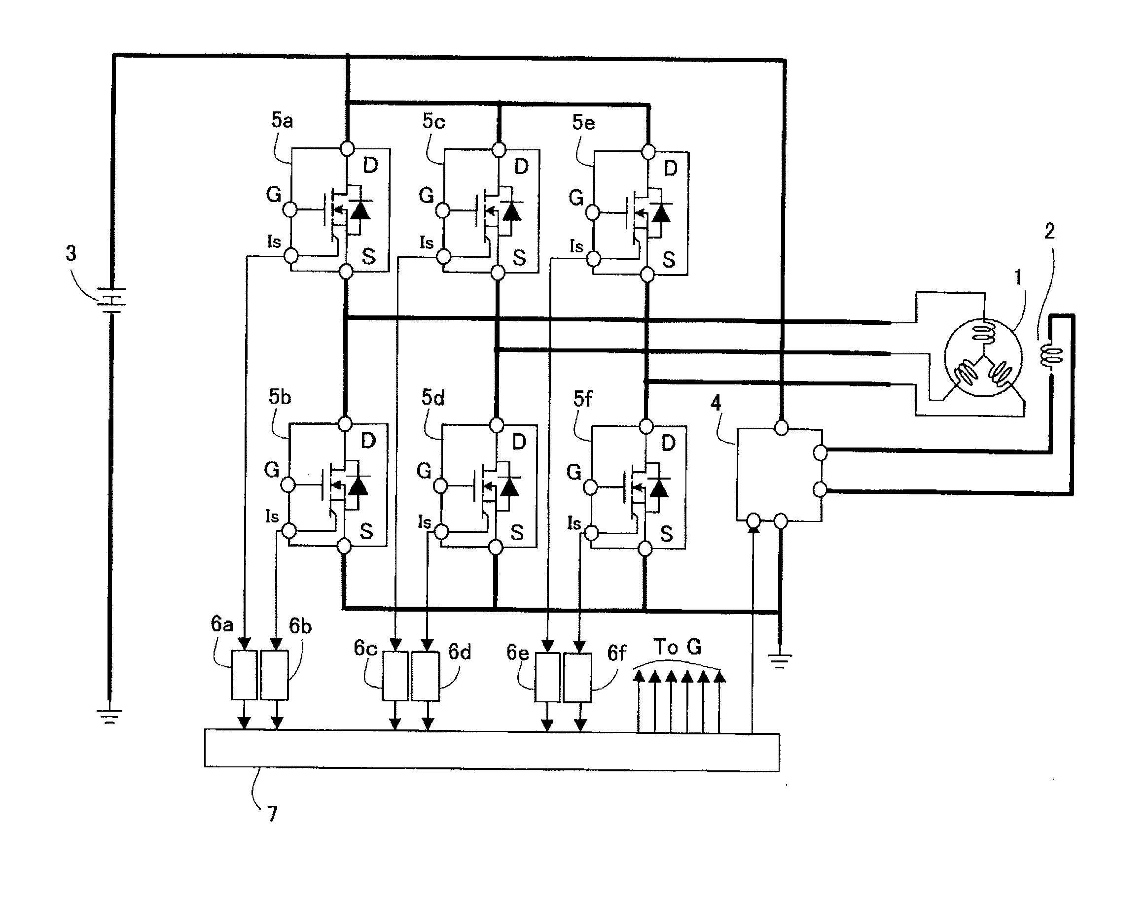
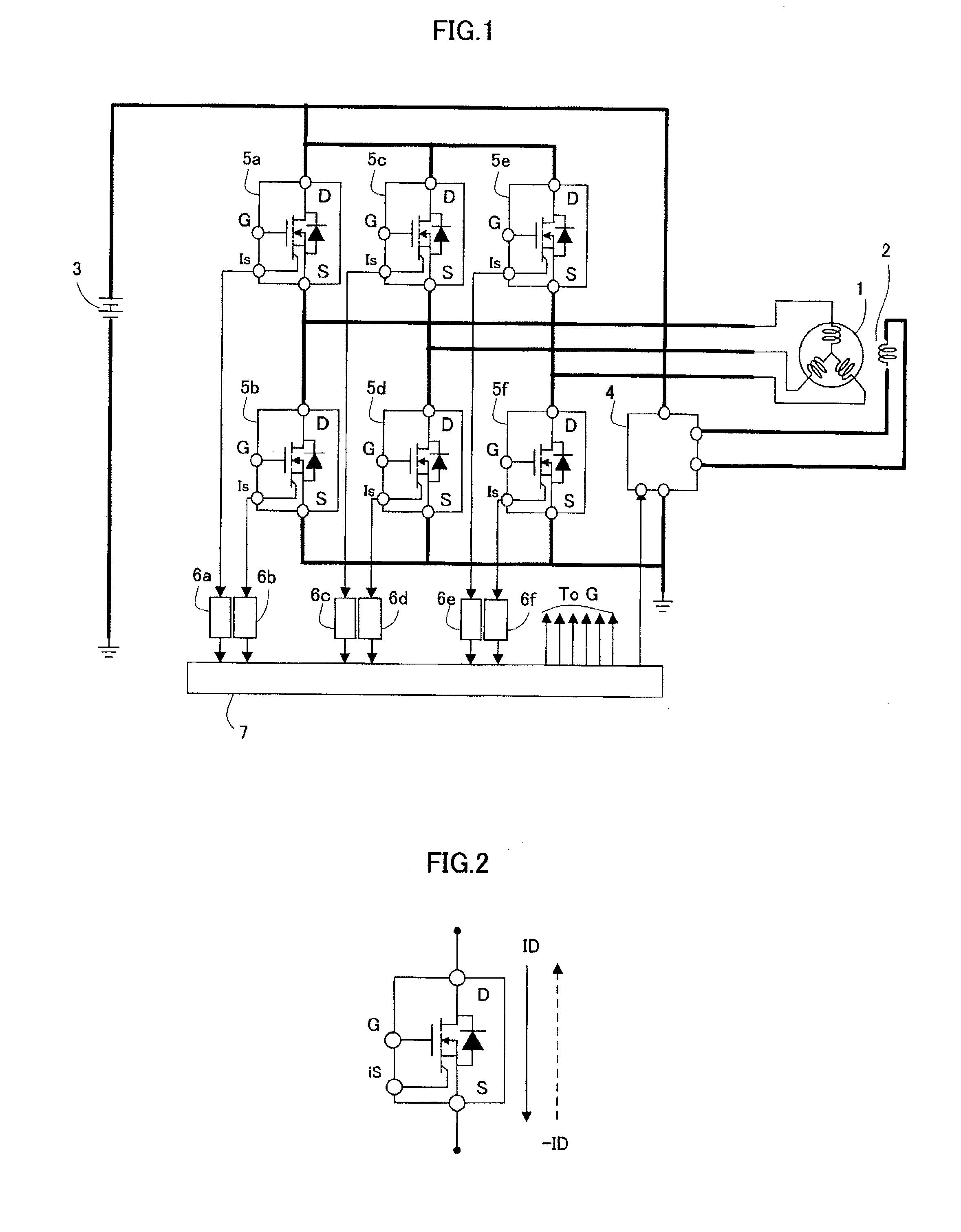
[0018]FIG. 1 is a diagram showing a configuration of the entire charging circuit using a bridge rectifier circuit according to Embodiment 1.In FIG. 1, the reference numeral 1 denotes an armature winding that constitutes a motor-generator; the reference numeral 2, a field winding of the same; the reference numeral 3, a vehicle-mounted battery; the reference numeral 4, a field-winding on / off switch that takes control of a current flowing through the field winding 2; and the reference numerals 5a to 5f, MOSFETs that are connected between the motor-generator and the battery 3 and constitute a rectifier circuit that takes control of a current flowing through the armature winding 1. In the figure, D represents a drain terminal; S, a source terminal; and G, a gate terminal. Furthermore, Is represents a terminal from which a current flowing between the drain and the source of one of the FETs, generally referred to as sensing FET or the like, is divided and taken out, which serves as a phase...


PUM


Abstract

A bridge rectifier circuit, which takes control of a current flowing through an armature winding of a motor-generator and a battery, includes rectifier elements each made of a MOSFET; phase current detection means that detect the amount and the direction of current flowing between the drain and the source of the FET; and a control means that takes on/off control of the FET by applying a control voltage between the gate and the source thereof; wherein when the phase current detection means detect a reverse current flowing through the FET exceeding a first predetermined value, the control means applies a control voltage between the gate and the source of the FET so as to turn on the FET.

Description

BACKGROUND OF THE INVENTION[0001]1. Field of the Invention[0002]The present invention relates to a bridge rectifier circuit used in a synchronous generator or a synchronous motor-generator, having an armature and a field winding, that is mostly mounted on a vehicle and serves as a starter-motor when starting the combustion engine as well as a generator after the engine start.[0003]2. Description of the Related Art[0004]In a synchronous generator or a synchronous motor-generator that has an armature and a field winding and serves as a starter-motor when starting the combustion engine as well as a generator after the engine start, to date, technologies have been disclosed in, for example, Japanese Patent Publication No. 2959640 (hereinafter referred to as Patent Document 1), in which power loss during generating and charging operations can be reduced using, as rectifier elements for the rectifier circuit, metal-oxide semiconductor field-effect transistors (hereinafter referred to as M...

Claims


Application Information

Patent Timeline
IPC IPC(8): H02P6/18H02J7/14H02M7/12
CPCH02M1/32H02M7/53871Y02B70/1491H02M2001/0009H02M2001/0048H02M7/53873H02M1/0009H02M1/0048Y02B70/10
Inventor WATANABE, TETSUSHITARUYA, MASAAKI
Owner MITSUBISHI ELECTRIC CORP
Why Eureka
Try Eureka