[0009]The object of the present invention consists in realizing a projector and also a method for projecting an image, wherein the imaging device is intended to supply an image that has little
distortion and is free of chromatic aberrations, and can be realized cost-effectively and compactly.
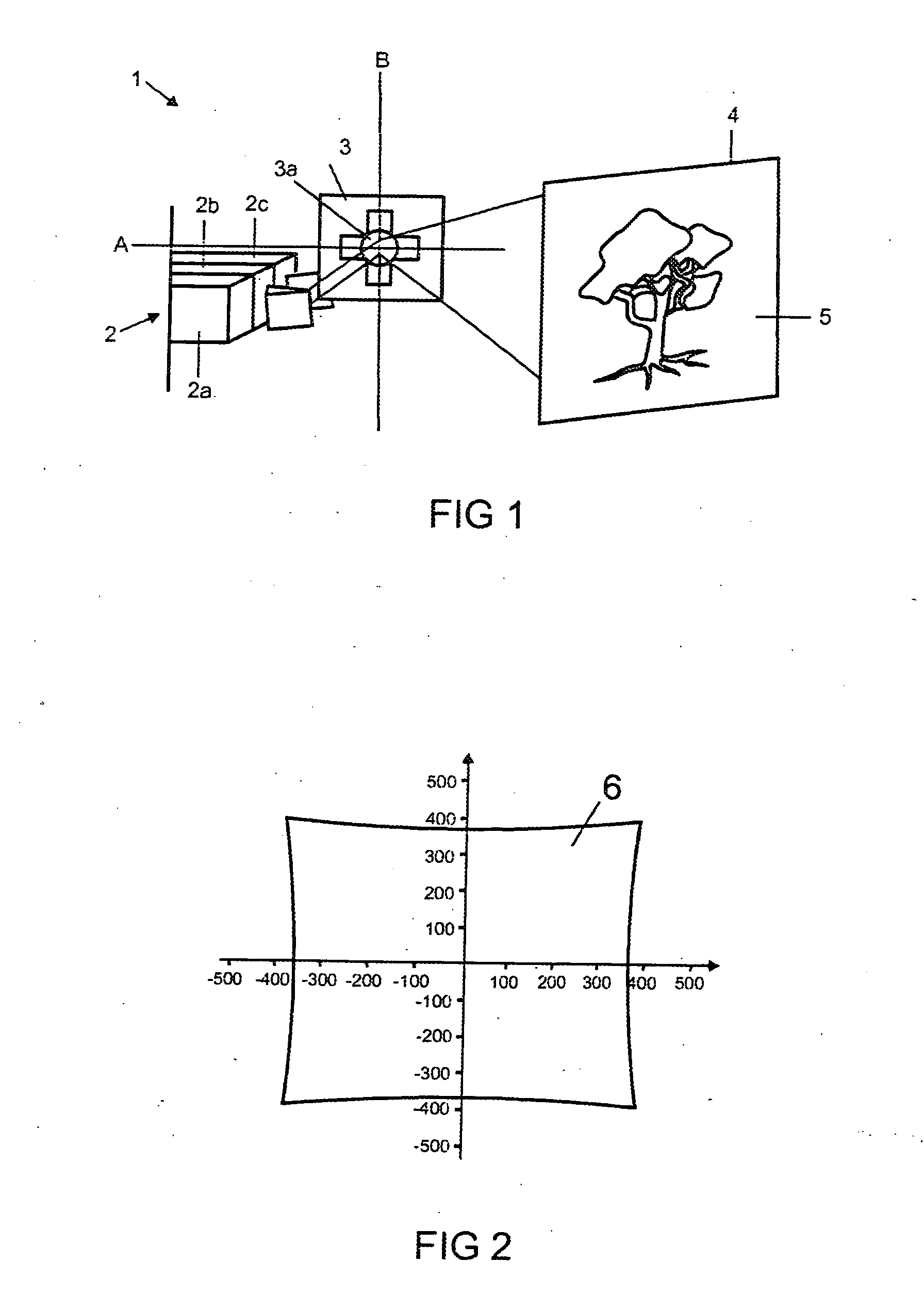
[0014]What is advantageously achieved by the projector according to the invention is that an image which is free of distortion or has little distortion in comparison with projection without an imaging device can be generated on the projection surface.
[0015]In particular, the projector is intended to be designed such that a beam
waist of the light bundle coming from the light source is placed onto the aperture of the deflection unit, the
diameter of the beam
waist being chosen to be somewhat smaller than the
diameter of the aperture, as a result of which excessive illumination of the deflection unit is prevented an no light losses are caused. The imaging scale of the mirror objective is chosen, in particular, such that the image of the aperture of the deflection unit on the projection surface approximately corresponds to the desired pixel size and is preferably somewhat smaller than the latter. Consequently, a beam waist will also lie on the projection surface or in the vicinity thereof. It has been found that the
depth of field of the image is not significantlyreduced by such imaging, and so it is not necessary to effect refocusing in the case of a realistic
projection distance with the mirror objective.
[0017]The mirror objective preferably has a
magnification of greater than or equal to one, such that the scanned
angular range downstream of the mirror objective is at least as large as the
angular range coming from the deflection unit. In the case of angular
magnification it is possible to use a deflection unit with a low maximum
deflection angle, as a result of which the deflection unit can be realized cost-effectively and with more
latitude for frequency and aperture size. In this case, the angular magnification by the mirror objective can be identical or different in magnitude for the two directions of the mirror oscillation. Thus, it may be provided, for example, that the
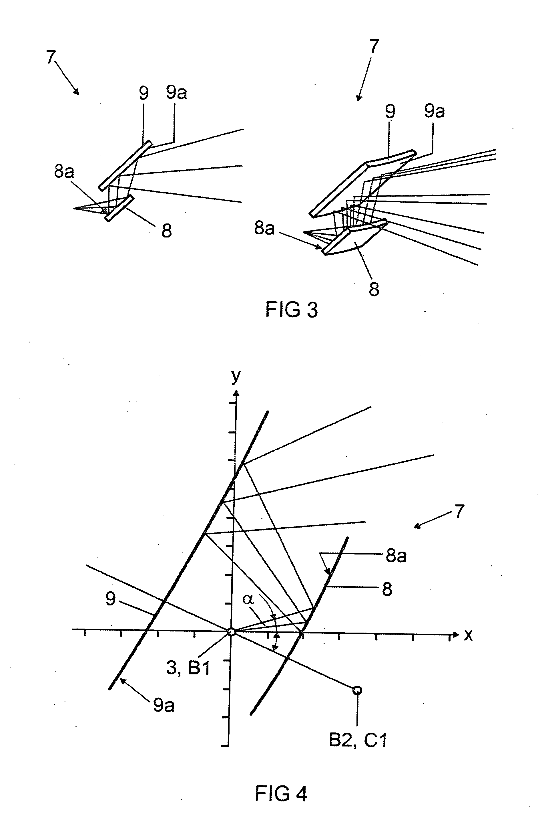
aperture angle of the scanned
angular range downstream of the deflection unit is 5° in the
horizontal and vertical directions, and the mirror objective is preferably embodied in such a way that the
aperture angle is 12° in the horizontal direction and 10° in the vertical direction.
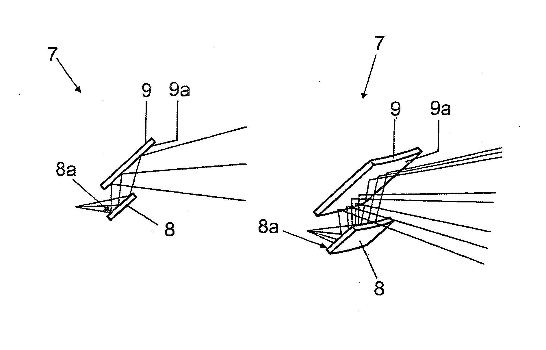
[0024]Preferably, the deflection unit is arranged at a focal point of the first of the hyperbolic mirror elements of the mirror objective or in the direct vicinity thereof. In particular, the deflection unit is intended to be arranged at a distance of less than 2 mm, in particular less than 1 mm, from the first focal point of the first mirror element. Preferably, the mirror objective is embodied in such a way that a second focal point of the first mirror element coincides with a first focal point of the second mirror element. In this case, too, it may preferably beprovided that the first focal point of the second mirror element is arranged at a distance of less than 2 mm, in particular at a distance of less than 1 mm, from the second focal point of the first mirror element. These defocusings allow a compromise between the effects of the
spherical aberration and the koma. In particular, the distance between the mirror elements is intended to increase as a result of the defocusing.
[0029]In one embodiment, the projector preferably has a pivoting or folding apparatus arranged on a housing of the projector or of a parent device, by means of which pivoting or folding apparatus the second mirror element is held and can be pivoted between a starting position, in which the rear side of said mirror element terminates with the housing, and a reflection position, in which emission of the light bundle from the housing is possible. In particular, it is provided that the second mirror element at least partly protrudes from the housing in the reflection position. In particular, in the housing, a passage opening for the light bundle is formed in the reflection position of the second mirror element, such that emission of the light bundle from the housing is made possible. In the initial position of the second of the mirror elements, said passage opening can preferably be closable by the pivotable second mirror element. In particular, the pivoting of the second mirror element into the reflection position causes the projector to be switched on.

