Heat radiation structure of electric apparatus

a technology of heat radiation structure and electric apparatus, which is applied in the direction of electrical apparatus construction details, lighting and heating apparatus, and semiconductor/solid-state device details, etc. it can solve the problems of increased heat releasing effect and complicated application of conventional heat radiation structure, and achieve the effect of suppressing lead terminal corrosion and low cos

Active Publication Date: 2010-12-02
SANYO DENKI CO LTD
View PDF17 Cites 12 Cited by
  • Summary
  • Abstract
  • Description
  • Claims
  • Application Information

AI Technical Summary

Benefits of technology

[0014]The heat conductive member may mainly be formed of a silicon or acrylic resin. Such materials are commercially available at low cost.
[0015]If at least one of the electronic components is mounted on the circuit substrate via a lead terminal, the lead terminal might be corroded due to a corrosive material contained in the heat conductive member. For example, if the heat conductive member is made of an acrylic resin, the lead terminal might be corroded due to an acrylic acid contained therein. For this reason, a heat-resistant protecti...

Problems solved by technology

It is complicated to apply such conventional heat radiation structure to a motor apparatus in which the rotational position sensor and circuit substrate are located on an axial line of a motor s...

Method used


Image

  • Heat radiation structure of electric apparatus
  • Heat radiation structure of electric apparatus
  • Heat radiation structure of electric apparatus

Examples


first embodiment

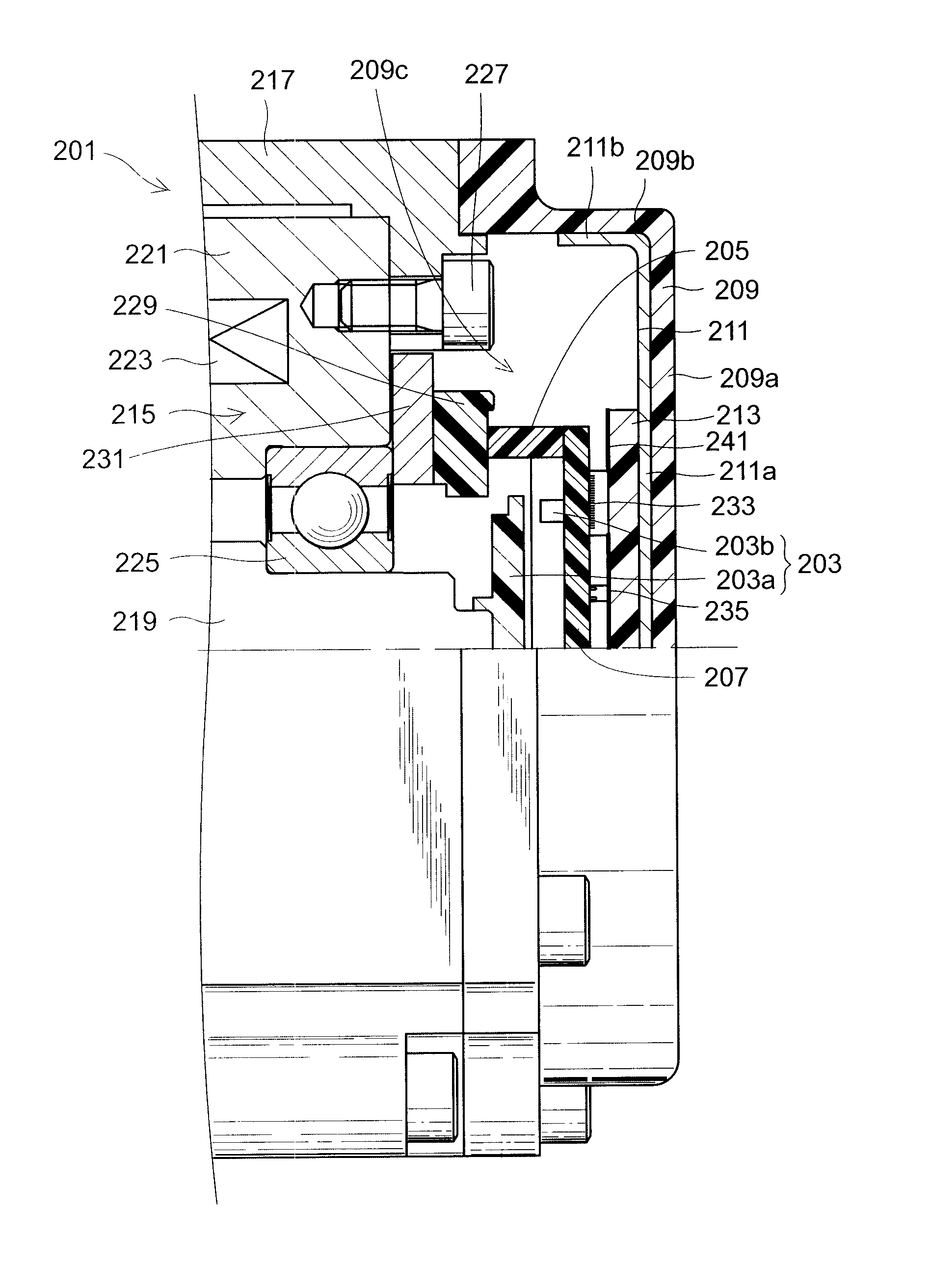
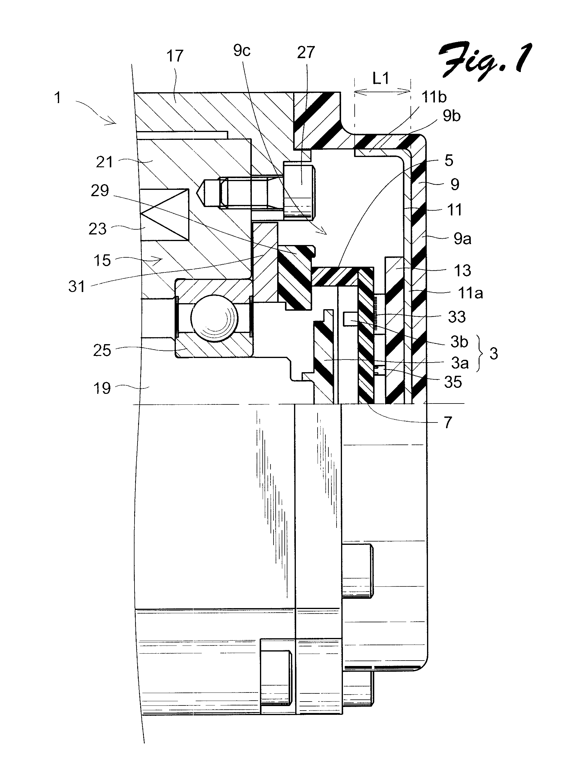
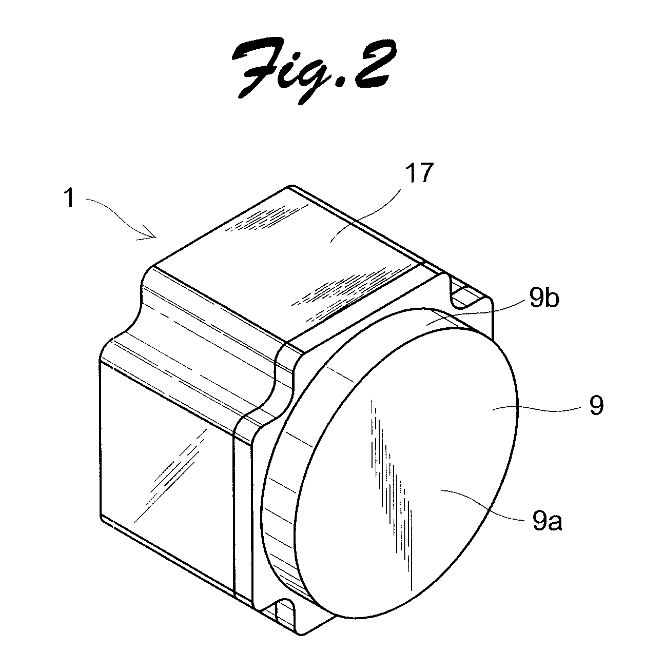
[0026]Embodiments of the present invention will now be described in detail with reference to the drawings. FIG. 1 is a partially cut-away view of a heat radiation structure of an electric apparatus according to the present invention, which is applied to a motor apparatus. FIG. 2 is a perspective view of the heat radiation structure of the electric apparatus of FIG. 1 as viewed from the side of a casing body 9 to be described later. As shown in FIG. 1, a motor apparatus provided with the heat radiation structure according to the present embodiment includes a motor section 1, a rotational position sensor 3, a circuit substrate supporting portion a circuit substrate 7, a casing body 9, an electromagnetic wave shielding member 11, and a heat conductive member 13. The motor section 1 includes an electromagnetic brake 15, a housing 17, and a shaft 19 whose one end projects from the housing 17. The electromagnetic brake 15 includes a brake core 21 and an electromagnetic coil 23. The brake ...

second embodiment

[0035]FIG. 5 is a partially cut-away view of a heat radiation structure of an electric apparatus according to the present invention. The heat radiation structure of the present embodiment is configured similarly to that of the motor apparatus of FIG. 1 except for an electromagnetic wave shielding member 111. Accordingly, parts whose configurations are similar to those of the corresponding heat radiation structure of FIG. 1 have reference numerals calculated by adding a number 100 to the reference numerals of the corresponding heat radiation structure of FIG. 1, and their explanations will be omitted. In the heat radiation structure according to the present embodiment, a second portion 111b of an electromagnetic wave shielding member 111 is configured not to be in contact with an inner wall surface of a peripheral wall portion 109b of a casing body 109. In this manner, a gap G is formed between the peripheral wall portion 109b and the second portion 111b. According to the present emb...


PUM


Abstract

A heat radiation structure of an electric apparatus provided herein is capable of readily releasing heat of electronic components to the outside and suppressing heat conduction to a rotational position sensor. A metal electromagnetic wave shielding member is fixed to a casing body of a casing. The electromagnetic wave shielding member includes a first portion that is connected to an opposed wall portion of the casing body to face a circuit substrate and a cylindrical second portion that is extending from a peripheral end of the first portion and along a peripheral wall portion of the casing body without being in contact with a housing. A heat conductive member having electrical insulating and heat conductivity properties as well as flexibility is disposed between the circuit substrate and the electromagnetic wave shielding member to closely contact both of the plurality of electronic components and the first portion of the electromagnetic wave shielding member.

Description

TECHNICAL FIELD[0001]The present invention relates to a heat radiation structure of an electric apparatus and, more specifically, to a heat radiation structure of an electric apparatus constituted from a motor apparatus including a rotational position sensor and a circuit substrate having one or more electronic components mounted thereon.BACKGROUND ART[0002]An existing motor (an electric device) typically comprises a rotational position sensor disposed on an axial end portion of a shaft of a motor section for detecting a rotational position of the motor section and a circuit substrate disposed outside of the end portion of the shaft on the axial line and having one or more electronic components mounted thereon. In such motor apparatus, detecting accuracy of the rotational position sensor is decreased or a life-span thereof is shortened if heat generated from electronic components is conducted to the rotational position sensor. Accordingly, how to release the heat generated from elec...

Claims


Application Information

Patent Timeline
IPC IPC(8): H05K7/20
CPCH02K9/22H02K11/33H02K11/01H02K11/21H01L23/3737H01L23/42H01L23/433H01L23/552H02K11/0141H02K9/223H02K5/04H05K7/20H02K7/003H02K2211/03
Inventor MIYASHITA, TOSHIHITOHIOKI, HIROSHICHIKYU, MASAKAZU
Owner SANYO DENKI CO LTD
Why Eureka
Try Eureka