Planar lipid bilayer array formed by microfluidic technique and method of analysis using planar lipid bilayer

Active Publication Date: 2010-12-02
THE UNIV OF TOKYO
View PDF2 Cites 16 Cited by
  • Summary
  • Abstract
  • Description
  • Claims
  • Application Information

AI Technical Summary

Benefits of technology

[0014]In view of the above-described problems, the present invention is intended to provide a planar lipid bilayer array formed by microfluidic technique and a method of analysis using

Problems solved by technology

However, handling membrane proteins such as ion channels, pumps, receptors, and transporters has been challenging as they only function when embedded in a lipid layer, i.e., a fundamental structure of all bio-membranes (see Non-Patent Document 3).
However, both methods require the experienc

Method used


Image

  • Planar lipid bilayer array formed by microfluidic technique and method of analysis using planar lipid bilayer
  • Planar lipid bilayer array formed by microfluidic technique and method of analysis using planar lipid bilayer
  • Planar lipid bilayer array formed by microfluidic technique and method of analysis using planar lipid bilayer

Examples


embodiments

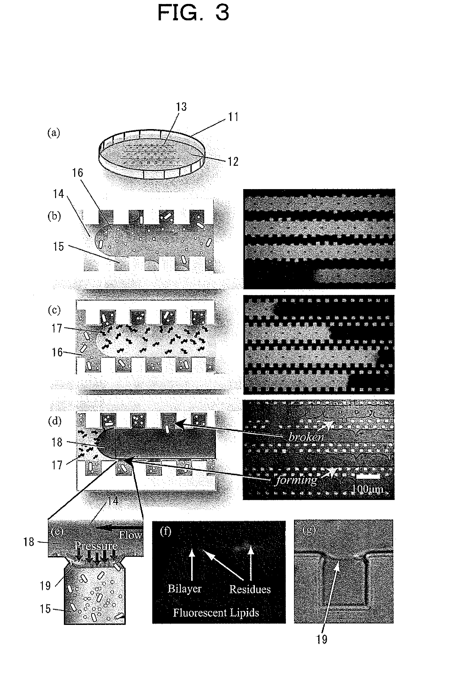
[0040]Hereinbelow, embodiments of the present invention will be described in detail.

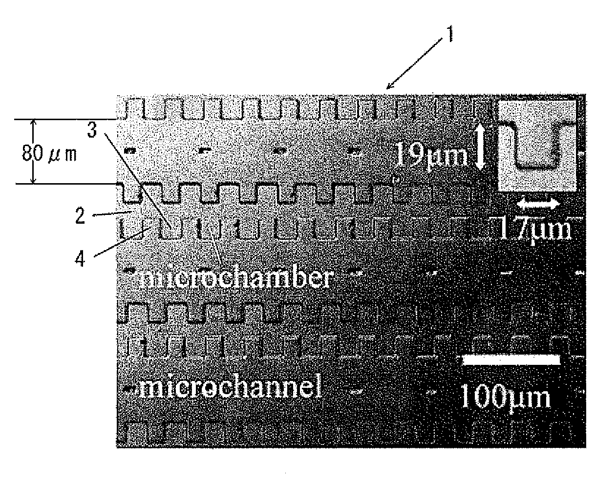
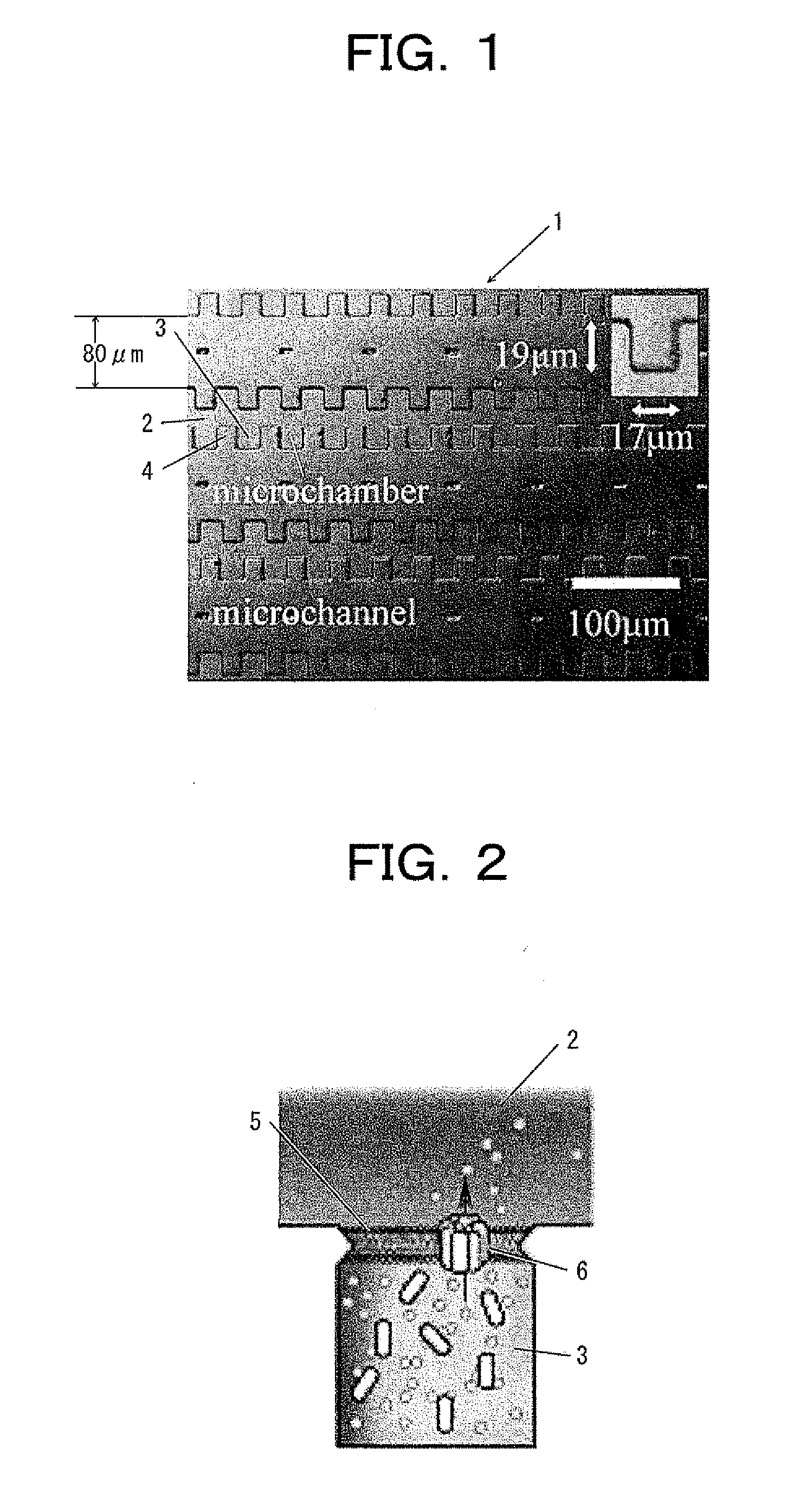
[0041]FIG. 1 is a conceptual diagram of microchannels having microchambers of a PDMS device illustrating an embodiment of the present invention. FIG. 2 is a diagram showing the microchamber sealed with a planar lipid bilayer.

[0042]In these figures, reference numeral 1 denotes a PDMS (Polydimethylsiloxane) device, 2 denotes a microchannel formed in the PDMS device 1, and 3 denotes a microchamber having an aperture alternately arranged on both sides of the microchannel 2. Although the both sides of the microchannel 2 are exemplified as side walls of the microchannel herein, the both sides of the microchannel 2 may refer to top and bottom walls of the microchannel. Here, each microchannel 2 is 7 μm in height, and the size of each microchamber 3 is 17 μm in width and 19 μm in height, for example.

[0043]Here, although the smaller membrane area of a planar lipid bilayer 5 formed on the aperture of the micro...


PUM


Abstract

There is provided a planar lipid bilayer array formed by microfluidic technique and a method of analysis using the planar lipid bilayers, providing the advantages such as portability, decreased analysis time, a smaller amount of required reagents, and parallel automation with high reproducibility. The planar lipid bilayer array formed by microfluidic technique is a planar lipid bilayer array formed by microfluidic technique (PDMS device) 1 saturated with water by preliminarily immersing in water, comprising microchannels 2 connected to an inlet of a microfluidic channel and arranged in parallel, and microchambers 3 having apertures on both sides of the microchannel 2.

Description

TECHNICAL FIELD[0001]The present invention relates to a planar lipid bilayer array formed by microfluidic technique and a method of analysis using the planar lipid bilayers, and in particular, to a planar lipid bilayer array formed by microfluidic technique for membrane protein analysis and a method of analysis of the membrane proteins using the same.BACKGROUND ART[0002]With the growing number of sequenced genomes, there has been a greater opportunity for proteome research (see Non-Patent Document 1). After the success of the DNA array chips which brought a revolution in genome researches, the “protein array chips” that are capable of high-throughput analysis of the expression and interaction of proteins are greatly sought after (see Non-Patent Document 2). Specifically, studies focusing on the functionality of membrane proteins are important since they are vital in regulating the transport of various molecules in and out of cells.[0003]However, handling membrane proteins such as io...

Claims


Application Information

Patent Timeline
IPC IPC(8): C40B30/00C40B40/04
CPCB01L3/5027B01L3/502738B01L2200/0605B01L2200/0642B01L2200/0673B01L2300/041B01L2300/0864B01L2400/0487G01N33/54306G01N33/54366G01N33/92G01N2405/04C40B60/00
Inventor TAKEUCHI, SHOJISUZUKI, HIROAKIOTA, SADAOTAN, WEI-HEONG
Owner THE UNIV OF TOKYO
Why Eureka
Try Eureka