Circuit and method for driving motor

a technology of circuit and motor, applied in the direction of motor/generator/converter stopper, electronic commutator, dynamo-electric converter control, etc., can solve the problem of reducing magnetic sensitivity, unable to use high-magnetically sensitive materials, and unable to use soft switching techniques using this difference in such an arrangemen

Inactive Publication Date: 2010-12-09
ROHM CO LTD
View PDF3 Cites 28 Cited by
  • Summary
  • Abstract
  • Description
  • Claims
  • Application Information

AI Technical Summary

Benefits of technology

[0010]Such an arrangement enables the motor to perform a soft-switching operation according to the rotational speed of the motor even in a situation in which the Hall signal has no effective sloping region.

Problems solved by technology

However, where such Hall effect sensor components are integrated on the driving circuit using the silicon process, highly magnetically sensitive material cannot be employed, unlike an arrangement employing Hall effect sensors in the form of external components.
This leads to a problem of reduced magnetic sensitivity.
If signal processing is performed to cancel out the offset component, the difference in the magnetic field before and after the switching timing, which is to be detected by the Hall effect sensor, cannot be detected, and thus the soft switching technique using this difference cannot be used in such an arrangement.
Similarly, in a case in which a sensorless technique using back electromotive force is employed, only the timing at which the back electromotive force is generated is detected, and thus, like the aforementioned arrangement employing Hall effect sensors, the soft switching technique according to the change in the magnetic field cannot be used in such an arrangement.

Method used


Image

  • Circuit and method for driving motor
  • Circuit and method for driving motor
  • Circuit and method for driving motor

Examples


modification 1

[Modification 1]

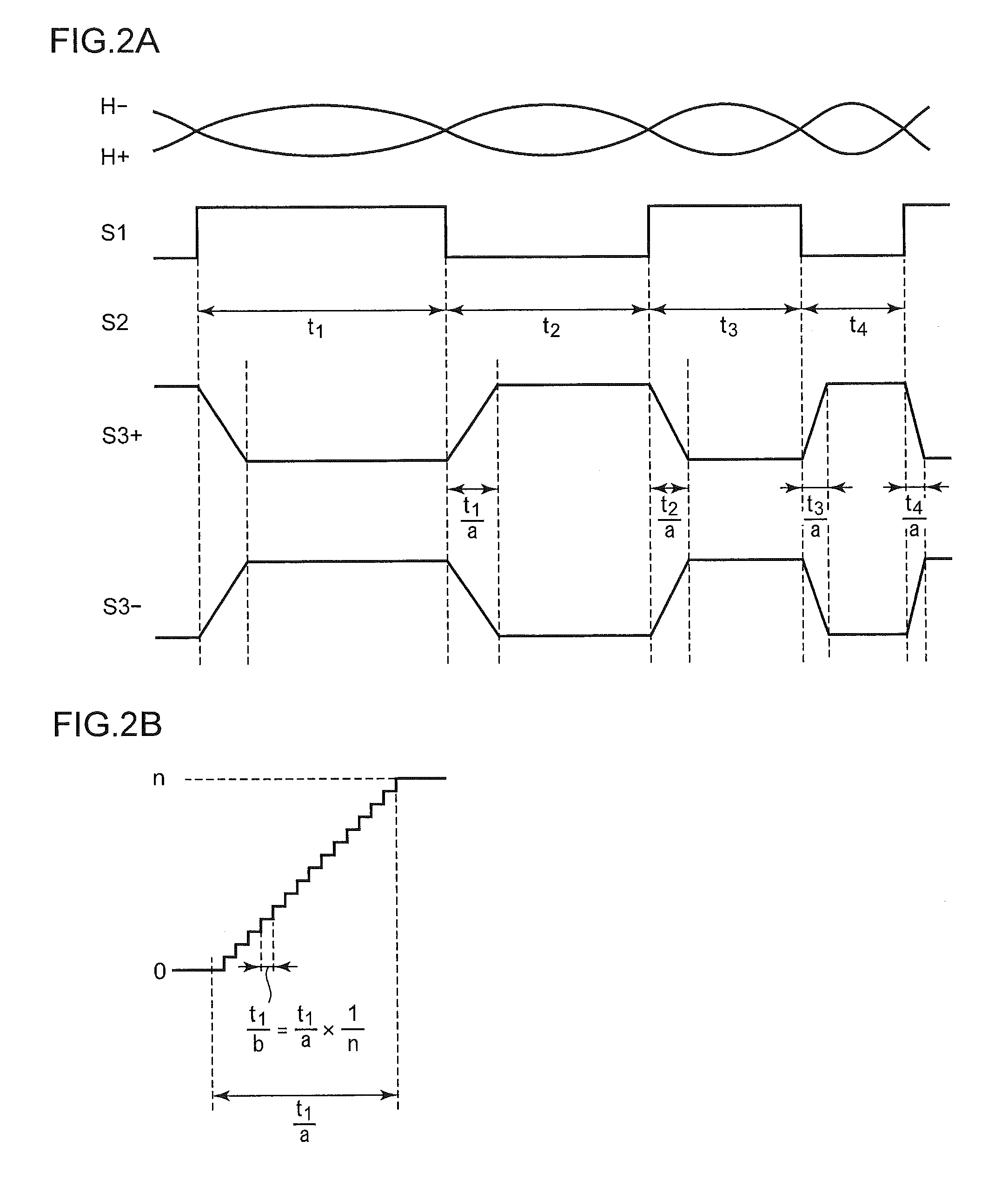
[0056]Also, the slope setting unit 24 may set the slope of the sloping region by performing statistical processing on a predetermined number of values α of the cycle signal S2. Examples of the statistical processing include simple averaging, weighted averaging, etc. By setting the slope based upon the period t averaged over a predetermined number of measurements, such an arrangement provides a stable rotational operation of the motor 50.

modification 2

[Modification 2]

[0057]Description has been made in the above-described embodiment regarding an arrangement in which the duration of each sloping region of the driving waveform is set in proportion to the rotational period of the motor. However, the present invention is not restricted to such an arrangement. For example, the slope setting unit 24 may include a table which defines the relation between the cycle period and the duration of the sloping region, and may operate with reference to the table, thereby providing the same processing. With such an arrangement including such a table, the duration of the sloping region can be adjusted more finely. Thus, such an arrangement provides advantages from the perspective of noise and power consumption.

modification 3

[Modification 3]

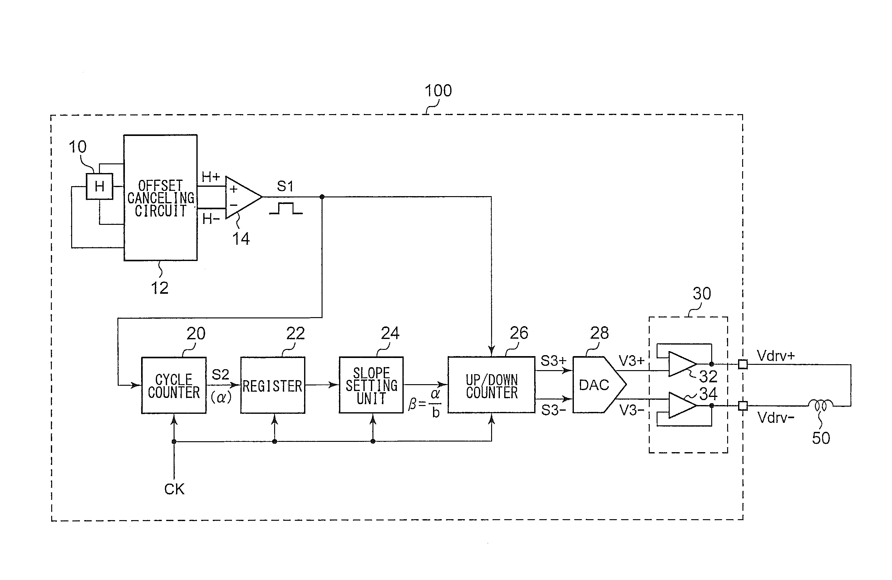
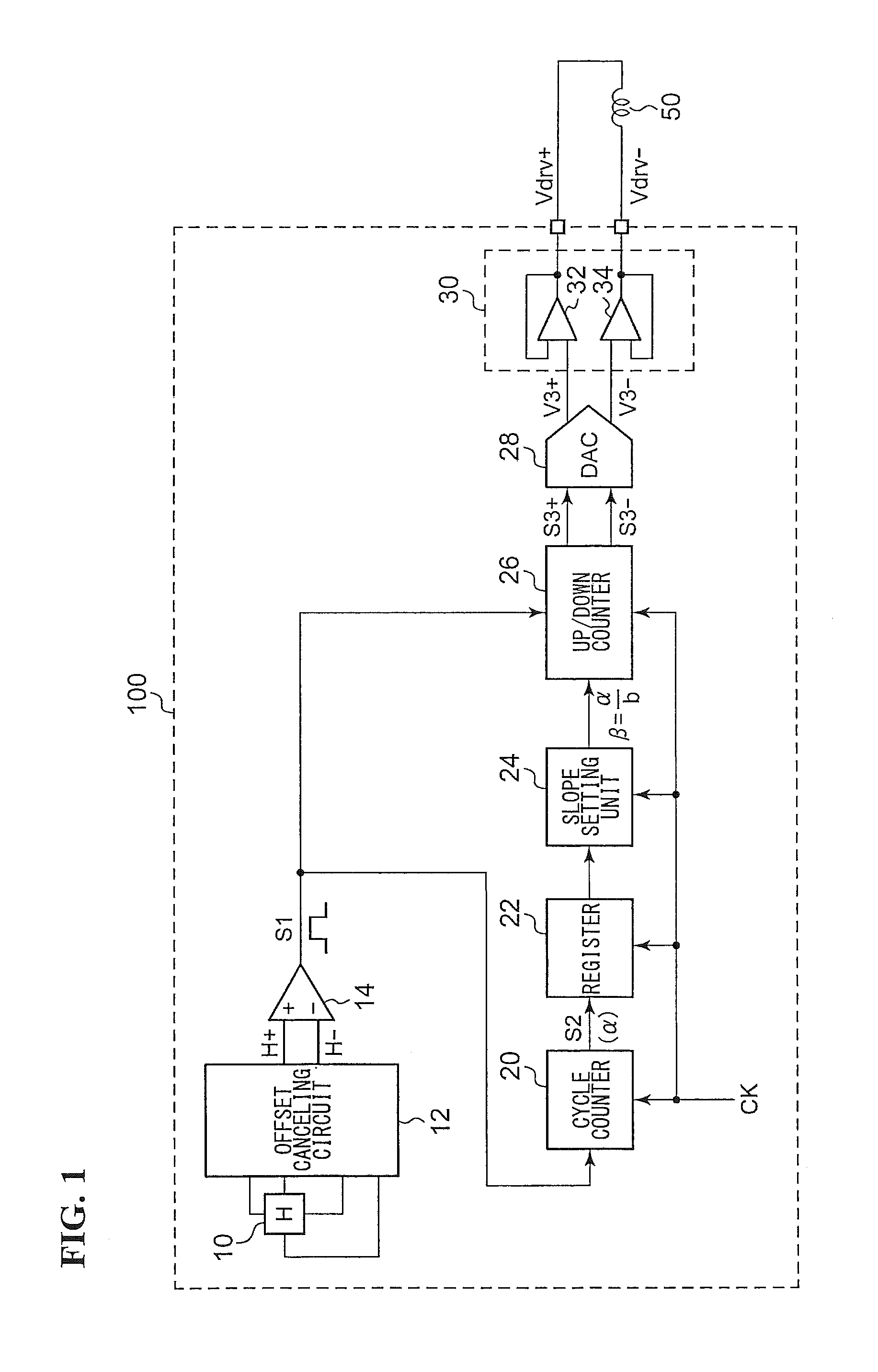
[0058]Description has been made regarding an arrangement in which the Hall effect sensor 10, the offset canceling circuit 12, and the comparator 14 are monolithically integrated together with other circuit blocks. Also, a part of the Hall effect sensor 10, the offset canceling circuit 12, and the comparator 14 may be provided in the form of external components.

[0059]The logic level settings such as the high level and the low level have been described in the embodiments for exemplary purpose only. Various modifications can be conceived for the configuration of such a logic circuit block, which are encompassed within the scope of the present invention.


PUM


Abstract

A cycle counter generates a cycle signal which indicates, in the form of a digital value, the cycle of Hall signals H+ and H− that indicate the position of a rotor of a motor to be driven. An up/down counter repeatedly alternates between counting “up” and counting “down” upon detecting phase transitions that occur in the Hall signals, and generates a digital driving waveform signal having a sloping region the slope of which is set according to the cycle signal. A D/A converter receives the driving waveform signal, and converts the driving waveform signal thus received into an analog voltage. A driving unit supplies a driving voltage to the motor according to the analog voltage thus received.

Description

BACKGROUND OF THE INVENTION[0001]1. Field of the Invention[0002]The present invention relates to a driving technique for a motor.[0003]2. Description of the Related Art[0004]As a cooling fan motor, a spindle motor for rotating an optical or a magnetic disk, or a capstan motor employed in a tape recorder apparatus, a brushless DC motor is employed. A typical brushless motor includes a rotor having a permanent magnet and a stator having a coil. With such a brushless DC motor, the electric current to be supplied to the coil is controlled so as to excite the coil, thereby rotationally driving the brushless DC motor.[0005]Techniques for detecting the rotational position of the rotor of a brushless DC motor are known, examples of which include techniques using Hall effect sensors or techniques for a sensorless driving operation using back electromotive force which occurs when phase transmission occurs. The Hall effect sensors generate a pair of Hall signals (which will be collectively ref...

Claims


Application Information

Patent Timeline
Patent Type & Authority Applications(United States)
IPC IPC(8): H02P6/16H02P6/20H02P6/08H02P6/06
CPCH02P2209/07H02P6/142H02P6/15
Inventor NAKAMURA, MASAHIRO
Owner ROHM CO LTD
Why Eureka
Try Eureka