Temperature tolerant magnetic linear displacement sensor

a technology of magnetic linear displacement and temperature tolerance, applied in the direction of galvano-magnetic hall-effect devices, magnetic field measurement using permanent magnets, instruments, etc., can solve the problems of increasing the cost of alignment of fibers, increasing the complexity, and increasing the cost of the alignment, so as to reduce the sensitivity and linear change in the magnetic field

Active Publication Date: 2010-12-09
LITTELFUSE INC
View PDF23 Cites 22 Cited by
  • Summary
  • Abstract
  • Description
  • Claims
  • Application Information

AI Technical Summary

Benefits of technology

[0009]The linear motion sensor of this invention comprises two substantially identical pairs of simple stacked dipole magnets arranged as mirror images across a gap. Each stack of two magnets comprises an outer shorter magnet and an inner longer magnet, wherein each magnet is a simple two pole bar magnet, and the smaller outer magnets are centered on the respective inner larger magnets. The poles of the smaller outer and larger inner magnets are oriented the same in each pair, and opposite with respect to the opposed pair of magnets. The shape of the magnets results in the magnetic fields produced by each pair of magnets being substantially outside of the magnets themselves, so...

Problems solved by technology

This displacement can be measured with many different sensing technologies over a large range of accuracies, with different levels of complexity, and at a wide range of costs.
These materials, such as quartz, steel, Invar® alloy, glass or ceramics generally require special machining techniques to manufacture and thus are more expensive.
Capacitive sensors are used with both conductive and nonconductive target materials but...

Method used


Image

  • Temperature tolerant magnetic linear displacement sensor
  • Temperature tolerant magnetic linear displacement sensor
  • Temperature tolerant magnetic linear displacement sensor

Examples


Embodiment Construction

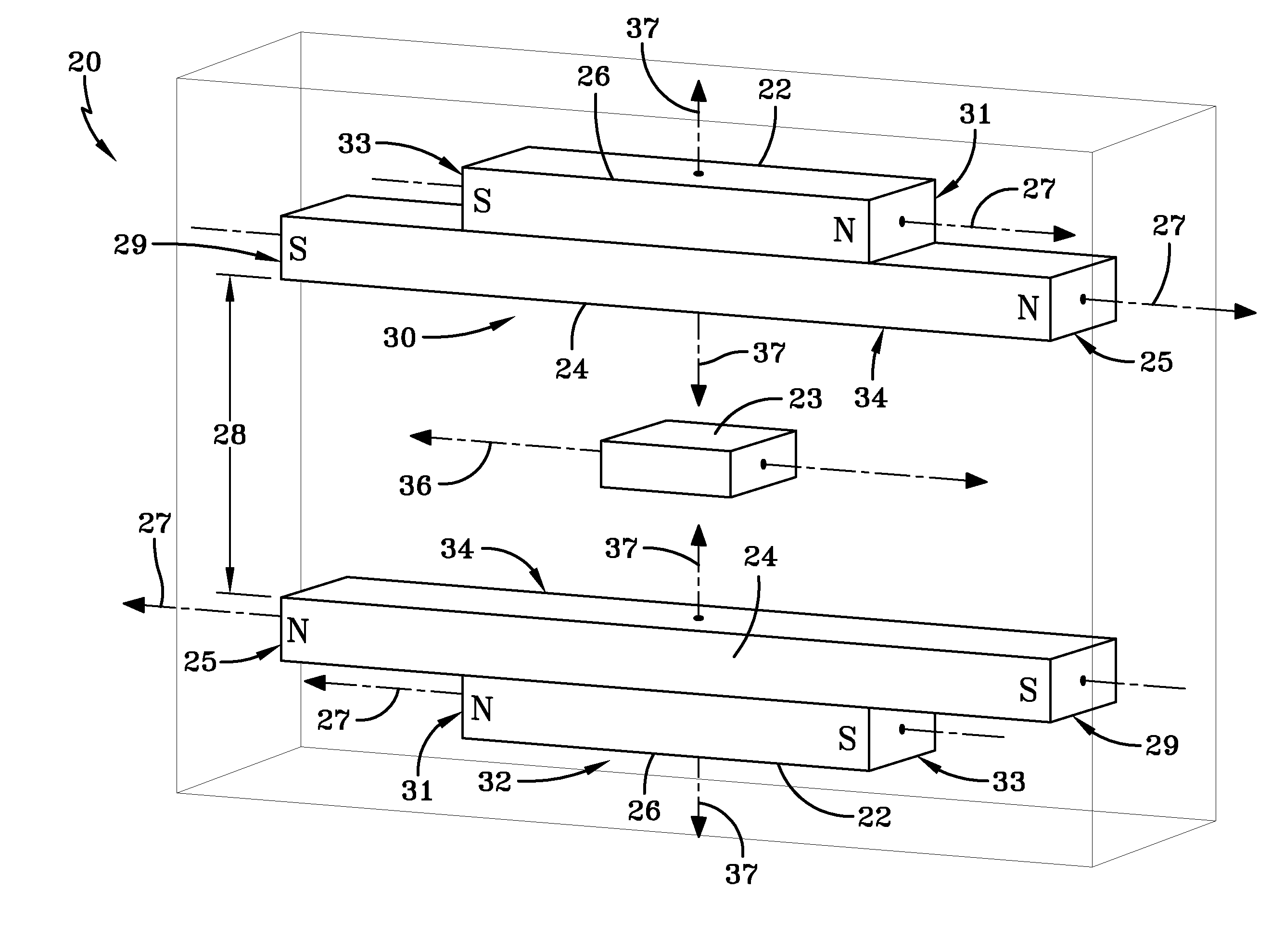
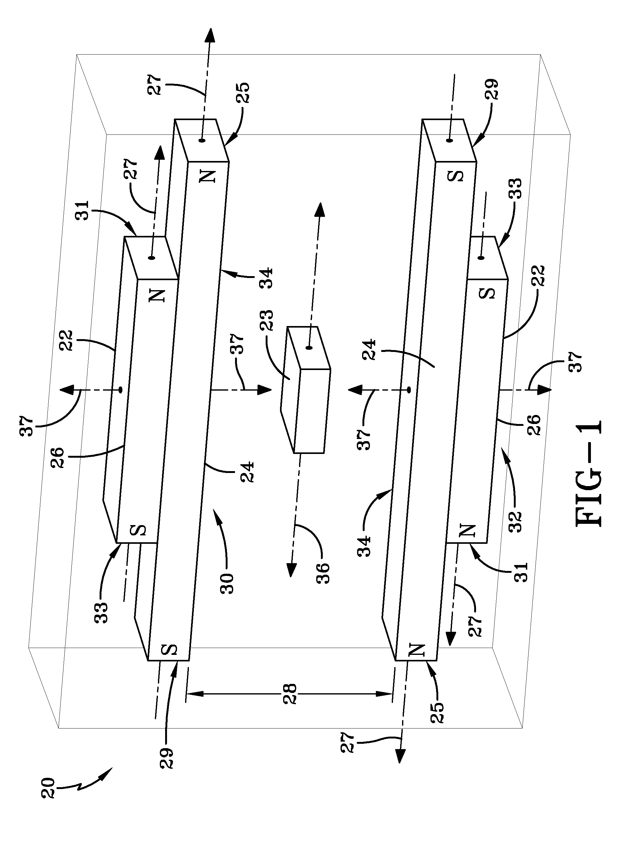
[0017]Referring more particularly to FIGS. 1-3, wherein like numbers refer to similar parts, a magnetic linear position sensor 20 is shown in FIG. 1. The sensor 20 is constructed from two pairs 22 of opposed magnets, and a magnetic field sensor 23. Each magnet pair 22 is a stack formed from a long magnet 24 approximately 23 mm long and a short magnet 26 approximately 12.2 mm long and centered on the long magnet. As shown in FIG. 1, the long magnets 24 face each other to define a gap 28 which is between the magnetic pairs 22. Each long magnet 24 and each short magnet 26 is a simple bar magnet having one north pole N and one south pole S. Each long magnet 24 extends between a north end 25 and a south end 29. Similarly each short magnet 26 extends between a north end 31 and a south end 33. The upper pair of magnets 30 is arranged with the poles oriented S-N, and the lower pair of magnets 32 is arranged with the poles oriented N-S such that there is an attractive force between the magne...


PUM


Abstract

A linear motion sensor has two pairs of opposed spaced apart stacks of two simple two-pole bar magnets. Each stack has one shorter outer magnet and one longer inner magnet, with the outer magnets centered on the inner magnets. The poles of the magnets are oriented the same in each pair, but opposite with respect to the other pair. The shape of the magnets results in the magnetic fields produced by each pair of magnets being substantially outside of the magnets themselves, so that the load line for the combined magnets is above the knee in its B/H material demagnetization curve. The pairs of magnets define a gap therebetween in which a magnetic field sensor is mounted for travel. The shorter magnets are about one half the length of the longer magnets such that the magnetic field in the gap varies substantially linearly as the sensor moves along the gap.

Description

BACKGROUND OF THE INVENTION [0001]The present invention relates generally to position measurement devices in general and more particularly to devices used to sense linear motion using magnetic fields.[0002]It is often necessary to measure the position or displacement of two elements relative to each other. This displacement can be measured with many different sensing technologies over a large range of accuracies, with different levels of complexity, and at a wide range of costs.[0003]Some common apparatus for measuring linear displacement employ linear encoders, capacitive sensors, eddy current sensors, a linear variable differential transformer, photoelectric or fiber optic sensors, or magnetic field sensors. Linear encoders use a glass or metal ruler that is made of a high stability material so that changes in temperature do not affect measurement accuracy. These materials, such as quartz, steel, Invar® alloy, glass or ceramics generally require special machining techniques to man...

Claims


Application Information

Patent Timeline
IPC IPC(8): G01B7/14
CPCG01R33/038G01D5/145
Inventor STUVE, STEVEN R
Owner LITTELFUSE INC
Why Eureka
Try Eureka