Pipeline geometry sensor

a sensor and pipeline technology, applied in the field of pipeline vehicles, can solve the problems of bulky components of rotary potentiometers and shaft encoders, metal loss regions, distortions such as dents, and achieve the effect of high resolution and high density of sensor arms

Inactive Publication Date: 2010-12-09
PII LIMITED
View PDF3 Cites 16 Cited by
  • Summary
  • Abstract
  • Description
  • Claims
  • Application Information

AI Technical Summary

Benefits of technology

[0017]The sensor module may include biasing means for biasing the sensor arm towards a deployed position relative to the support structure. The sensor arm may be resiliently biased towards the deployed position, for example, by leaf springs, torsion springs, a resilient bushing or the like. Thus, when the sensor module is mounted on the pipeline vehicle, the end of the sensor arm remote from the pipeline vehicle may abut the inner wall of a pipe. If a deformation in the pipe wall is encountered, the end of the sensor arm remote from the pipeline vehicle will move radially to conform to the inner wall of the pipe. This movement will cause relative movement between the magnetic flux sensor (e.g. mounted on the sensor arm) and the magnet mounted (e.g. mounted on the support structure), whereby the magnetic flux sensor registers a change in magnetic field. The change in magnetic field may permit the position of the sensor arm, and hence the geometry of the pipeline, to be determined. By positioning the magnet on the support structure for the sensor arm, the position of the magnet remains fixed relative to the body of the pipeline vehicle when the sensor module is mounted on the vehicle. Thus, the position of the magnet may be fixed relative to other magnets provided by other sensor modules, and the level of interaction between magnets on different sensor modules is unchanging (and can be calculated or measured). The effect of this interaction on the reading obtained from the magnetic flux sensor mounted on the sensor arm can therefore be compensated or corrected.
[0018]The magnetic flux sensor may be arranged on the sensor arm so that it is embedded within the arm. Similarly, the magnet may be mounted on the support structure so that it is at least partly embedded in this structure. Hence, a compact sensor module may be provided. Such compact sensors modules may be mounted on the surface of the pipeline vehicle in a closely-spaced arrangement, thus providing a high density of sensor arms on the pipeline vehicle. This arrangement allows the internal geometry of the pipeline to be determined with a high degree of resolution.

Problems solved by technology

Defects of particular importance include cracks, regions of metal loss (due to corrosion, for example), and distortions such as dents.
However, rotary potentiometers and shaft encoders are bulky components and can prevent sensor arms being placed close together.
Thus, when using these components, there is a limit to the number of sensor arms that can be provided on an outer surface of the pipeline inspection vehicle.
Hence the resolution with which the interior geometry of the pipeline can be determined is also limited.
Furthermore, rotary potentiometers and shaft encoders may be unsuitable for use in high pressure and dirty environments where they could be susceptible to damage due to the effects of pressure, or ingress of product or debris.

Method used


Image

  • Pipeline geometry sensor
  • Pipeline geometry sensor
  • Pipeline geometry sensor

Examples


Embodiment Construction

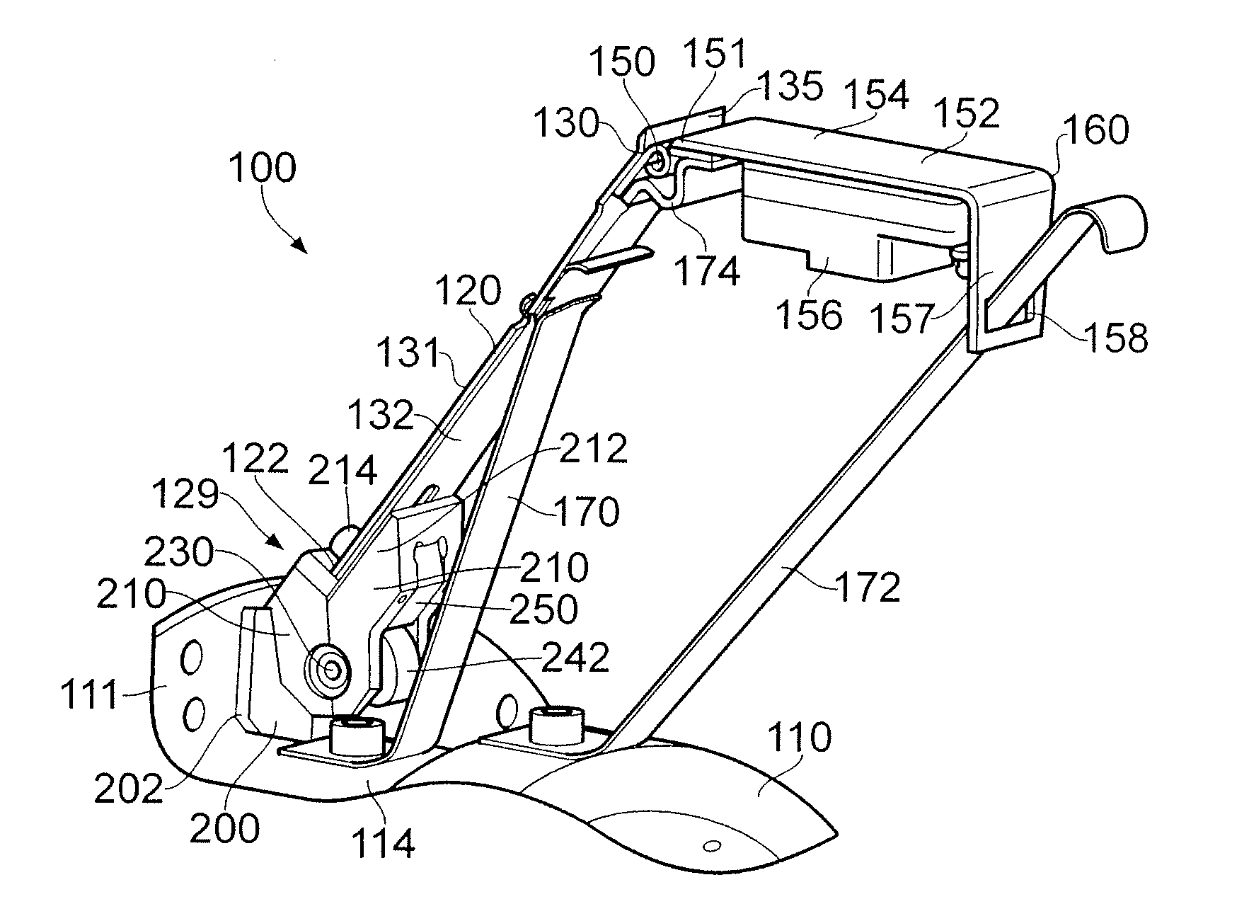
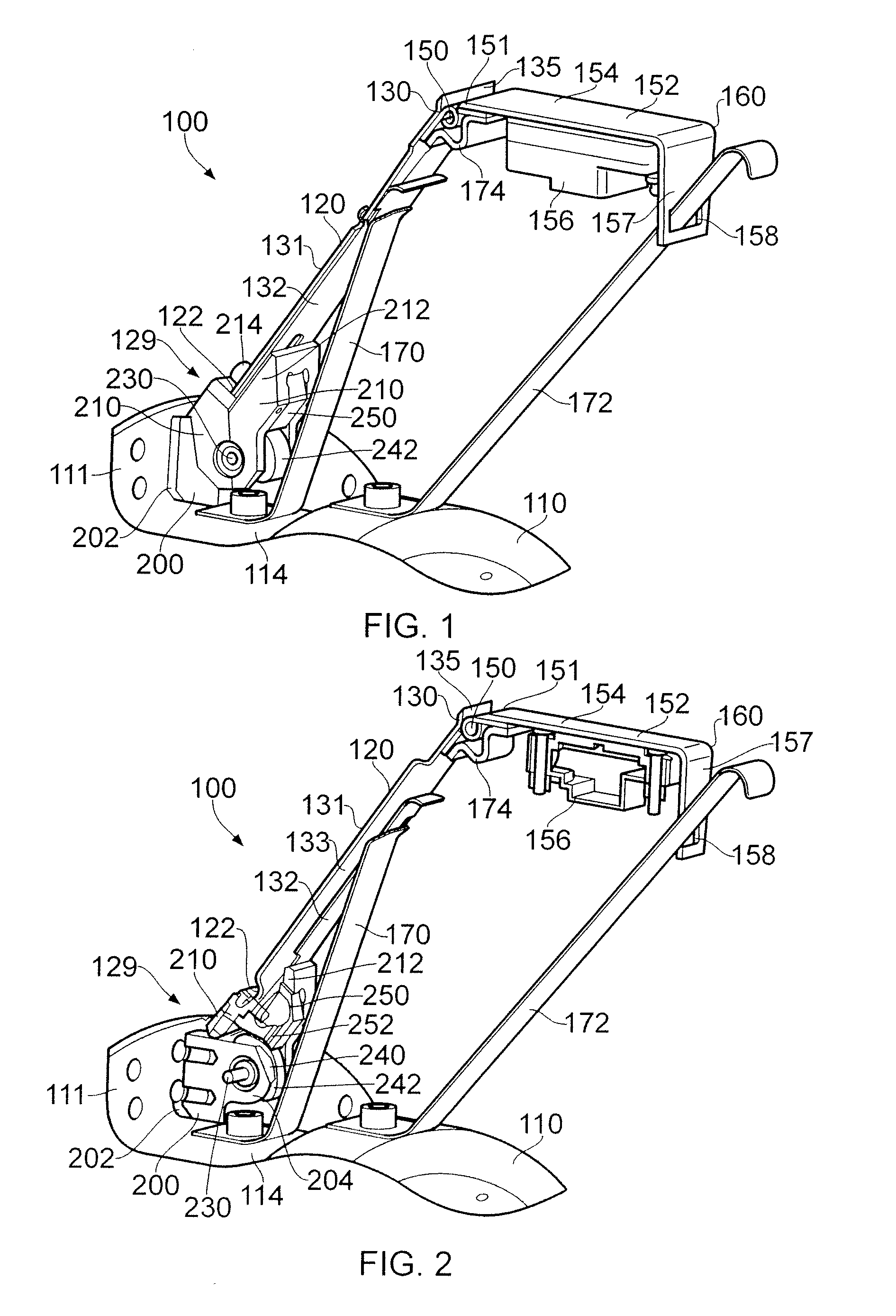
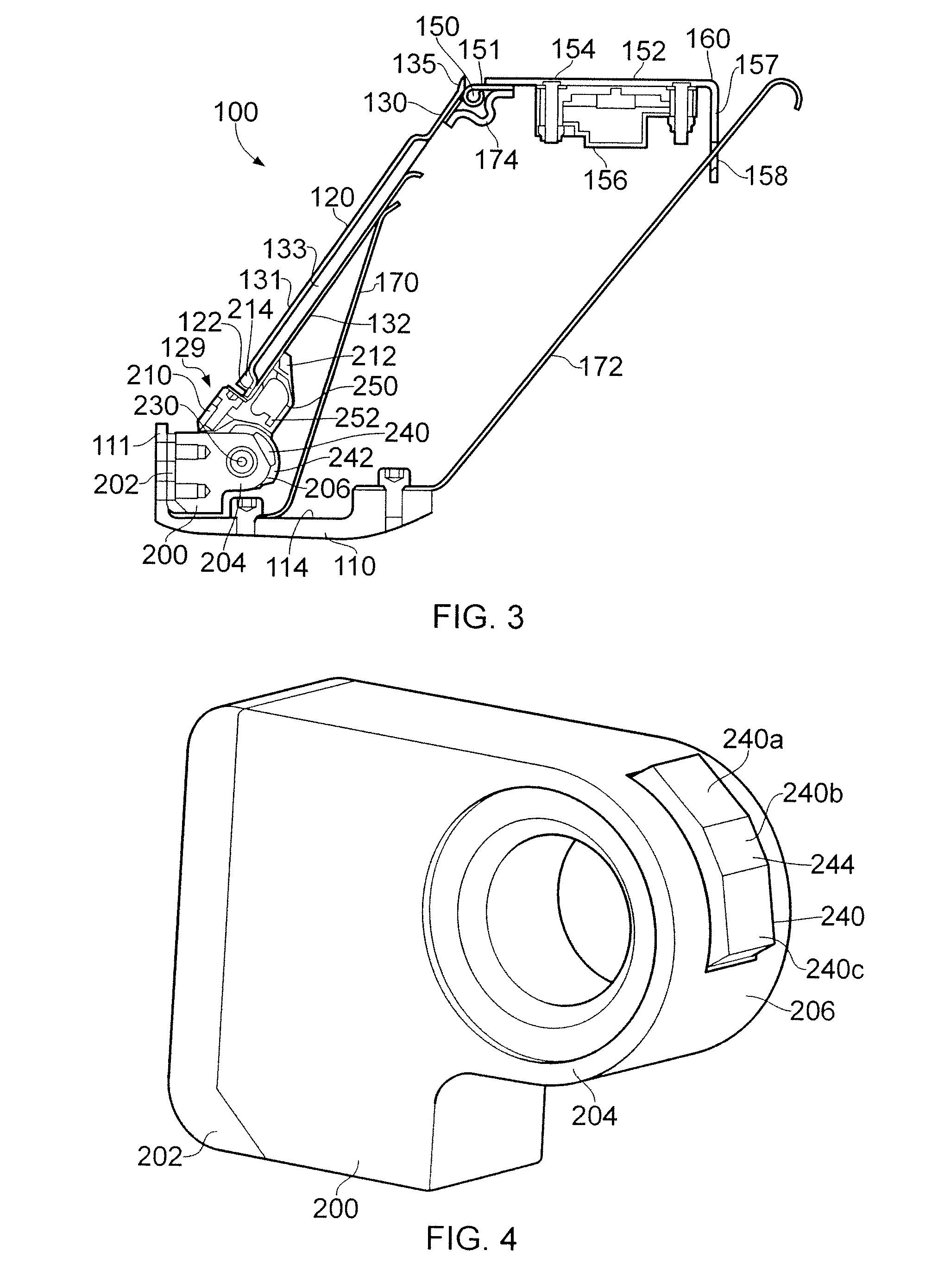
[0035]FIGS. 1, 2 and 3 illustrate a sensor module 100 according to an embodiment of the invention. The sensor module 100 is mounted on an upstanding flange 111 on an outer surface of a pipeline vehicle 110. Although not shown in FIGS. 1-3, a plurality of such inspection sensor modules 100 may be provided circumferentially around the pipeline vehicle 110, with each sensor module 100 extending laterally from the pipeline vehicle 110. When the pipeline vehicle 110 is being used for inspecting a pipeline, the inspection sensor modules 100 extend radially from the pipeline vehicle 110, and each inspection sensor module 100 abuts a portion of the inner wall of the pipeline. The sensor module 100 comprises a sensor arm 120 having a proximal end 122 that is connected to the pipeline vehicle 110 by a first hinge 129. The distal end 130 of the sensor arm 120 is connected to a sensor sledge 152 by a second hinge 150. The sensor sledge 152 has an inspection surface 154 for contacting (sliding r...


PUM

PropertyMeasurementUnit
thickaaaaaaaaaa
orientation angleaaaaaaaaaa
angleaaaaaaaaaa

Abstract

A sensor module (100) for a pipeline vehicle (110) is disclosed. The sensor module (100) includes an outwardly biased sensor arm (120) pivotally connected at a hinge (129) mounted on the vehicle (110), whereby the angle between the sensor arm (120) and pipeline vehicle (110) is representative of a pipeline dimension. A magnet (240) and magnetic flux sensor (252) are mounted in the sensor module (100) to move relative to one another as the sensor arm (120) pivots relative to the vehicle (110). Measurement of change in magnetic flux can permit determination of the angle between the sensor arm and the vehicle. The sensor module (100) may be mounted on an upstanding flange (111) via a compliant (deformable) layer (202) which permits lateral deflection of the module (100) relative to the vehicle (110).

Description

BACKGROUND OF THE INVENTION[0001]1. Field of the Invention[0002]The present invention relates to pipeline vehicles, e.g. vehicles adapted to travel within a pipeline for cleaning or inspection purposes. For example, the invention may relate to inspection sensor modules for pipeline inspection vehicles (known as pipeline pigs) which can determine the internal geometry of a pipeline.[0003]2. Summary of the Prior Art[0004]It is known to inspect the inside of a pipeline using a pipeline pig which may comprise one or more interconnected vehicles which pass down the pipe.[0005]Pipeline inspection vehicles typically comprise a main central body to which sensors or other components are mounted. The vehicles may be equipped with cleaning tools for removing debris and contamination from the wall of the pipeline, and sensors for determining the pipeline integrity.[0006]The pig may be towed along the pipeline, or be fitted with pressure plates which enable propulsion by a difference in pressure...

Claims


Application Information

Patent Timeline
Patent Type & Authority Applications(United States)
IPC IPC(8): G01N27/82
CPCB08B9/043G01D5/145G01B7/13B08B9/0551
Inventor HOULDLEY, PETERMUNDELL, PAUL ARTHUR
Owner PII LIMITED
Why Eureka
Try Eureka