

Liquid crystal panel and liquid crystal display
a liquid crystal display and liquid crystal technology, applied in the field of liquid crystal panels, can solve the problems of not being considered to have sufficient contrast, the display color variation with the viewing angle is significant, and the contrast is relatively low, so as to reduce light leakage and high contrast
- Summary
- Abstract
- Description
- Claims
- Application Information
AI Technical Summary
Benefits of technology
Problems solved by technology
Method used
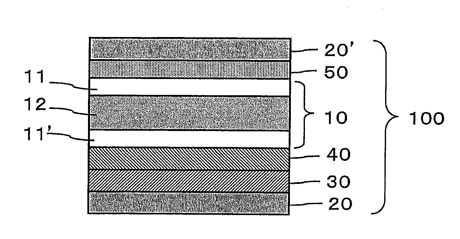
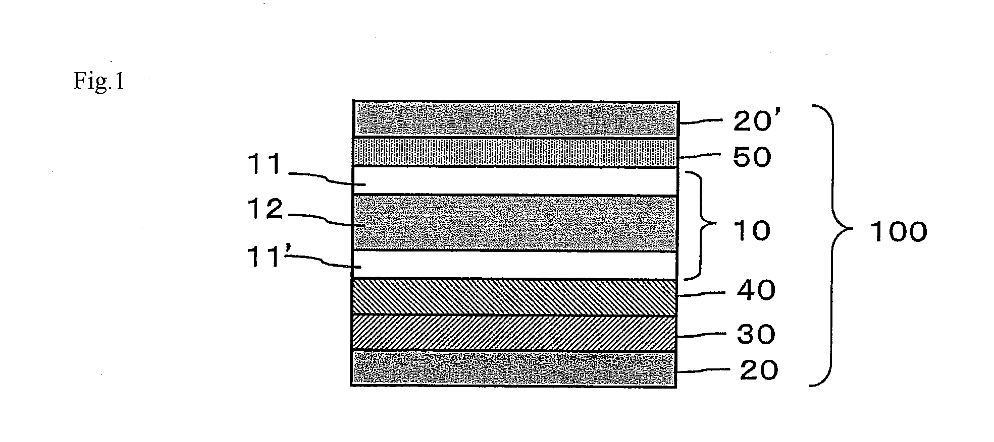
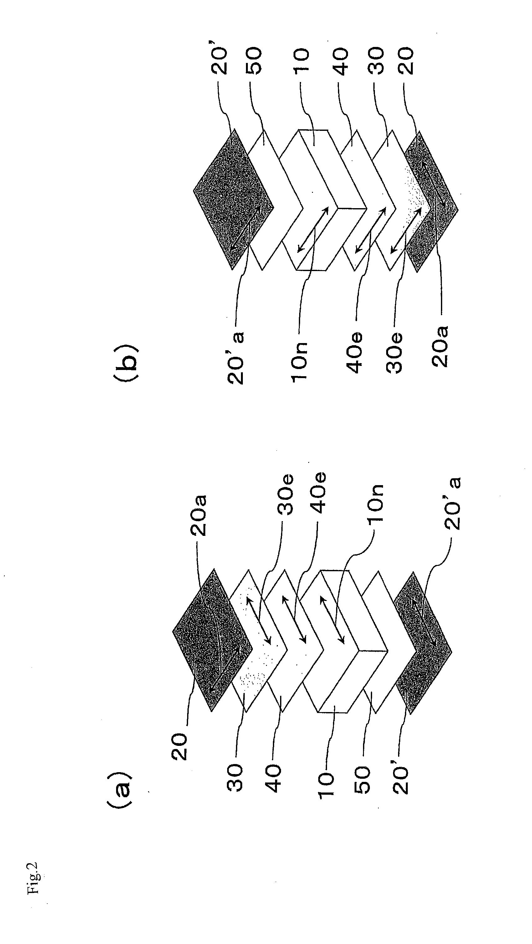
Image

Examples
examples
[0212]The invention is further described by the examples and comparative examples below. However, such examples are not to be construed as limitations of the invention. The measurement methods used in the examples are described below.
[Retardation Value and Three-Dimensional Refractive Index]
[0213]The measurement was performed using a retardation meter KOBRA-WPR (product name, manufactured by Oji Scientific Instruments) based on parallel Nicol rotation method at 23° C. with light at a wavelength of 590 nm. The retardation of the film was measured in the front (normal) direction and measured when the film was inclined by 40°. The refractive index nx in a direction where the in-plane refractive index was maximum, the refractive index ny in a direction perpendicular thereto, and the refractive index nz in the film thickness direction were each calculated from the measured values using the software installed in the system. These values and the thickness (d) were used to determine the in-...
examples of
Production of Anisotropic Optical Element
production example 1a
[0215]Using a tenter stretching machine, a commercially available polymer film (Zeonor Film ZF14-130 (trade name) manufactured by Optes Corporation, 60 μm in thickness, 136° C. in glass transition temperature) composed mainly of a cyclic polyolefin polymer was subjected to end-constraint uniaxial stretching in the width direction (transverse-direction stretching process) at a temperature of 158° C. so that the film width could be 3.0 times the original film width before the machine-direction stretching process. The resulting film was a negative biaxial plate having a fast axis in the feed direction. This negative biaxial plate is named retardation film 30A.
Production of Second Anisotropic Optical Element
PUM
| Property | Measurement | Unit |
|---|---|---|
| thickness direction retardation Rth3 | aaaaa | aaaaa |
| electric field | aaaaa | aaaaa |
| refractive indices | aaaaa | aaaaa |
Abstract
Description
Claims
Application Information