
Image-bearing member protecting agent, method of applying an image-bearing member protecting agent, protective layer forming device, image forming method, process cartridge, and image forming apparatus

a protection agent and image bearing technology, applied in the field of image bearing member protection agent, can solve the problems of deterioration of image bearing member, abraded solid lubricant contacting therewith, natural weakening of pressing force, etc., and achieve excellent quality of application.

Active Publication Date: 2010-12-09
RICOH KK
View PDF21 Cites 30 Cited by
  • Summary
  • Abstract
  • Description
  • Claims
  • Application Information

AI Technical Summary

Benefits of technology

[0027]The present invention has been made in light of the present circumstances. An object of the present invention is to provide an image-bearing member protecting agent capable of preventing abrasion of image bearing members, toner filming, smear of charging members and toner leakage and capable of maintaining its excellent coating quality for a long time, and a method of applying the image-bearing member protecting agent.
[0029]Still another object of the present invention is to provide an image forming method and an image forming apparatus, whereby an image excellent in quality can be stably obtained over a long period of time.
[0030]Yet another object of the present invention is to provide a process cartridge capable of obtaining an image excellent in quality.
[0054]According to the present invention, it is possible to maintain excellent quality of application of an image-bearing member protecting agent over a long period of time and to obtain images excellent in quality over a long period of time.

Problems solved by technology

Thus, there are various types of physical stress and electrical stress in each step in image formation, which deteriorate the image bearing member, charging member and cleaning member.
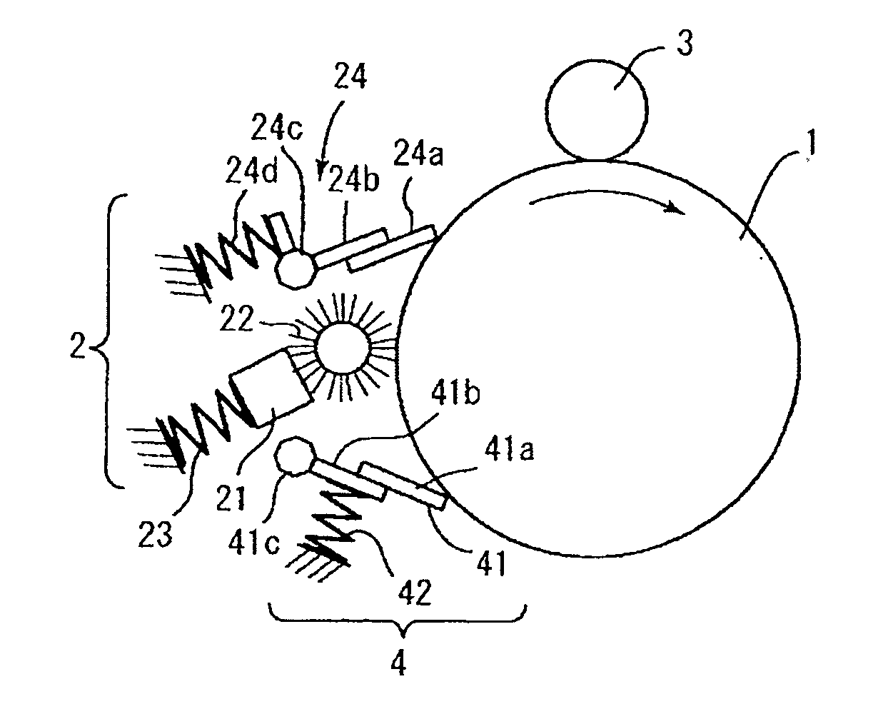
When the brush roller is driven to rotate, the solid lubricant contacting therewith is abraded, and thus scraped.
However, in the configuration where a solid lubricant is pressed against a brush roller with being in contact with a spring, the spring is extended as the solid lubricant is scraped off, and thus the pressing force naturally weakens.
Therefore, it is impossible to sufficiently protect the photoconductor or intermediate transfer belt.
However, it is known that with use of a solid lubricant block obtained by compression molding, it is impossible to prevent a reduction in consumption amount of the solid lubricant block over time even when a constant pressing force is maintained over a period of time (this case will be described hereinbelow in Comparative Examples).
However, in the proposal disclosed in JP-A No. 2007-65100, there is no description regarding a method for obtaining a solid lubricant block whose front side and back side are different in hardness.
If the hardness of the solid lubricant is changed by changing the composition thereof, the quality of application of the solid lubricant cannot be maintained at the same level over a long period of time.
Even when solid lubricant blocks, which are composed of the same material and have a different hardness, are obtained and used in a stacked structure, inflection points of consumption amount of the solid lubricant appear at boundaries between the blocks, and thus the quality of application of the solid lubricant cannot be maintained at the same level over a long period of time in this case as well.
Consequently, the lubricating properties of the cleaning blade and the image bearing member are impaired, and toner particles pass through therebetween (toner leakage), and thus defective images are formed.

Method used


Image

  • Image-bearing member protecting agent, method of applying an image-bearing member protecting agent, protective layer forming device, image forming method, process cartridge, and image forming apparatus
  • Image-bearing member protecting agent, method of applying an image-bearing member protecting agent, protective layer forming device, image forming method, process cartridge, and image forming apparatus
  • Image-bearing member protecting agent, method of applying an image-bearing member protecting agent, protective layer forming device, image forming method, process cartridge, and image forming apparatus

Examples


example 1

[0297]As an image-bearing member protecting agent, a fatty acid metal salt was molded by a compression-molding method so as to form a block having, on its surface, orientation just as in the above-mentioned image-bearing member protecting agent of the present invention, thereby preparing an image-bearing member protecting agent, which was used in the test. Note that a protecting agent-supply brush was pressed against a surface of the image bearing member, parallel to the oriented surfaces thereof. Zinc stearate (produced by NOF CORPORATION) was used for the fatty acid metal salt.

example 2

[0298]As an image-bearing member protecting agent, a fatty acid metal salt and an inorganic lubricant were mixed at a weight ratio of 8:2, molded by a compression-molding method so as to be formed in a block, having, on its surface, orientation just as in the above-mentioned image-bearing member protecting agent of the present invention, thereby preparing an image-bearing member protecting agent, which was used in the test. Note that a protecting agent-supply brush was pressed against a surface of the image bearing member, parallel to the oriented surfaces thereof. Zinc stearate (produced by NOF CORPORATION) was used for the fatty acid metal salt, and boron nitride (produced by Momentive Performance Materials Inc.) was used for the inorganic lubricant.

[0299]The transitive consumption amounts of image-bearing member protecting agents of Comparative Examples are illustrated in FIG. 14. The transitive consumption amounts of image-bearing member protecting agents of Examples according t...


PUM


Abstract

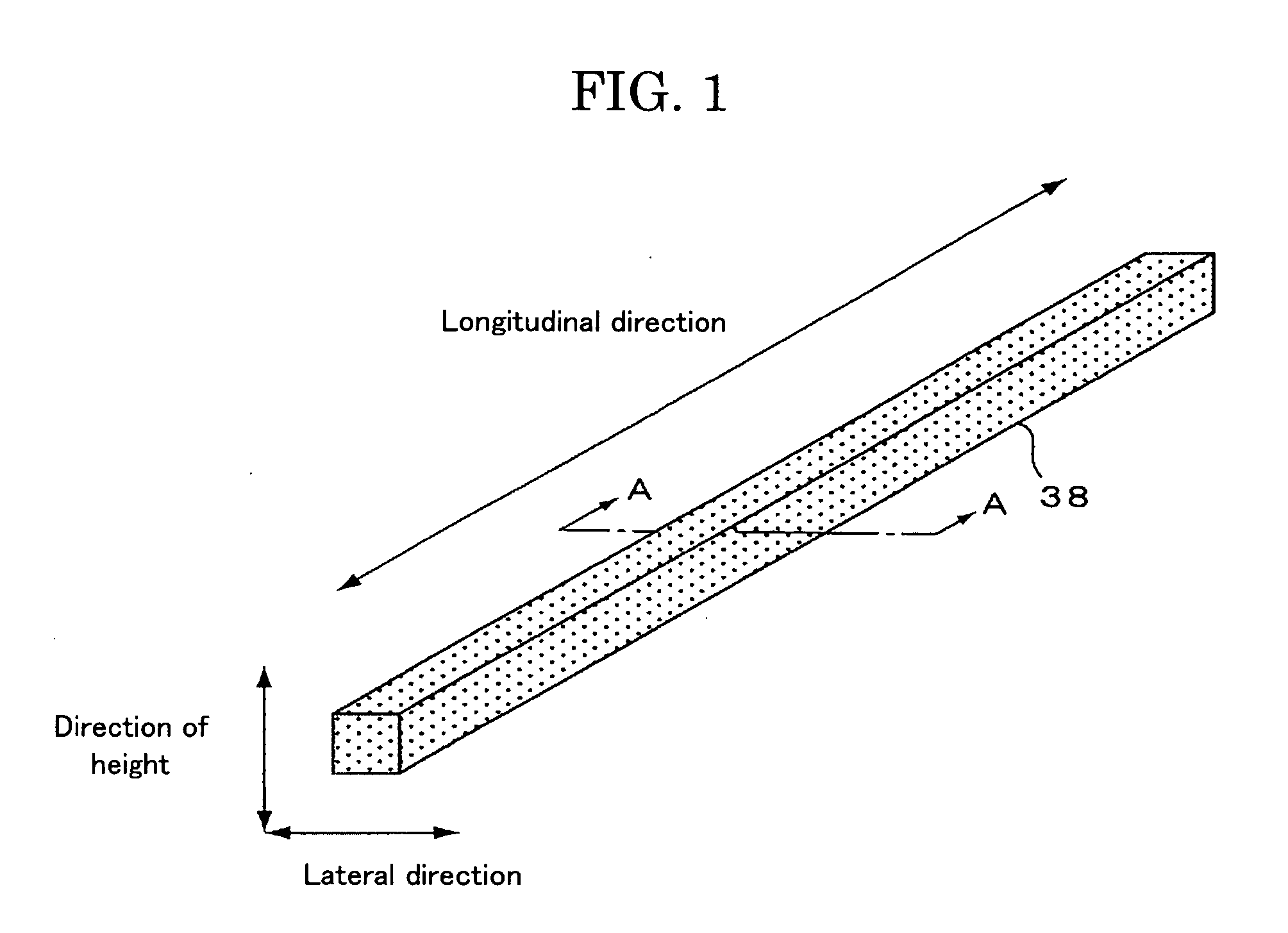
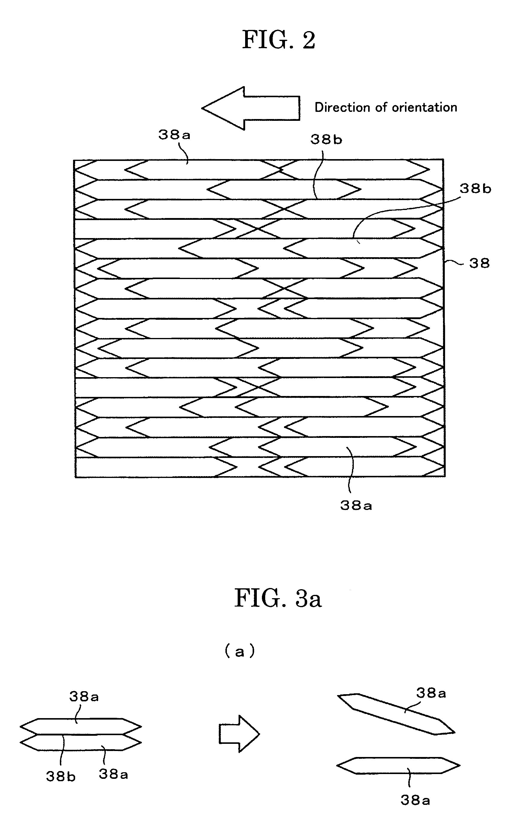
The present invention provides an image-bearing member protecting agent, which has a block shape and is used in an image forming process where the image-bearing member protecting agent is applied or attached to a surface of an image bearing member while being scraped off with a roll-shaped brush, the image-bearing member protecting agent including: a fatty acid metal salt, wherein the image-bearing member protecting agent includes a plurality of small blocks and has such an orientation that one or more of the small blocks are easily separated from other small blocks, and a plurality of oriented surfaces of the plurality of small blocks are arranged in a laminated state in a substantially same direction.

Description

BACKGROUND OF THE INVENTION[0001]1. Field of the Invention[0002]The present invention relates to an image-bearing member protecting agent for protecting the surface of an image bearing member, a method of applying the image-bearing member protecting agent, a protective layer forming device provided with the image-bearing member protecting agent, an image forming method using the image-bearing member protecting agent, a process cartridge provided with the protective layer forming device, a complex machine provided with the protective layer forming device or the process cartridge, and an image forming apparatus such as a complex machine provided with at least one of a printer, a facsimile and a plotter.[0003]2. Description of the Related Art[0004]Conventionally, in image formation based on an electrophotographic process, an electrostatically charged latent image, i.e., a latent electrostatic image, is formed on an image bearing member formed, for example, of a photoconductive material...

Claims


Application Information

Patent Timeline
IPC IPC(8): G03G21/00
CPCG03G5/0503G03G5/051G03G21/00G03G5/144G03G5/14704G03G5/142
Inventor TANAKA, SHINYANAKAI, HIROSHIHASEGAWA, KUNIOURAYAMA, TAICHI
Owner RICOH KK
Learn More