Wind turbine with two successive propellers

a wind turbine and propeller technology, applied in the direction of electric generator control, vessel construction, greenhouse gas reduction, etc., can solve the problems of limited efficiency when the wind speed is low, shortcoming of only having an acceptable electric power production, and relatively low general efficiency, so as to increase the general efficiency

Inactive Publication Date: 2010-12-09
ELENA ENERGIE
View PDF0 Cites 31 Cited by
  • Summary
  • Abstract
  • Description
  • Claims
  • Application Information

AI Technical Summary

Benefits of technology

[0013]The object of the invention consists in provid...

Problems solved by technology

These known wind turbines present the shortcoming of only having an acceptable electric power production for a relatively high wind speed, and of having a relatively low general efficiency on account of the low value of the ratio between the power collected by the rotary device at the throat and th...

Method used


Image

  • Wind turbine with two successive propellers
  • Wind turbine with two successive propellers
  • Wind turbine with two successive propellers

Examples


Embodiment Construction

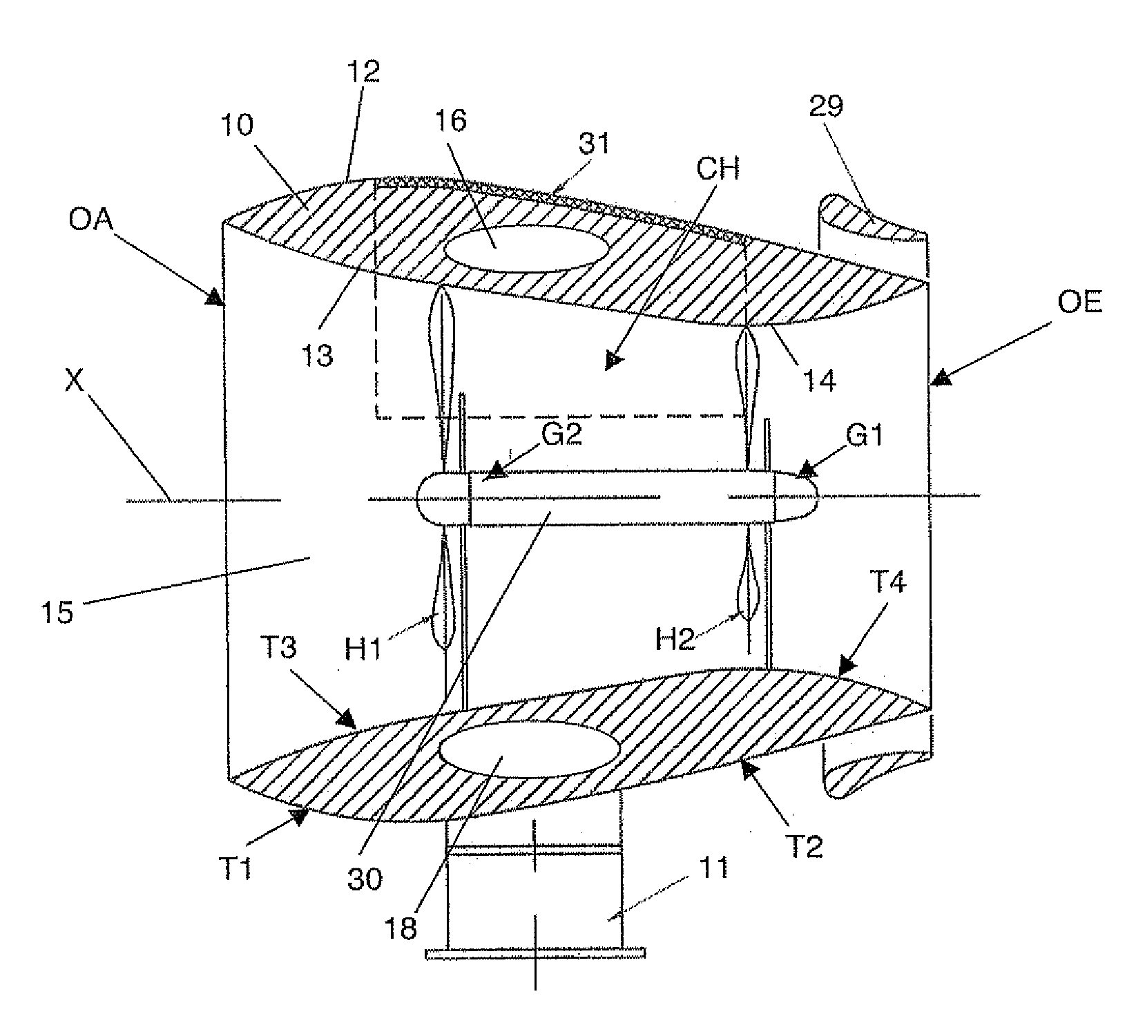
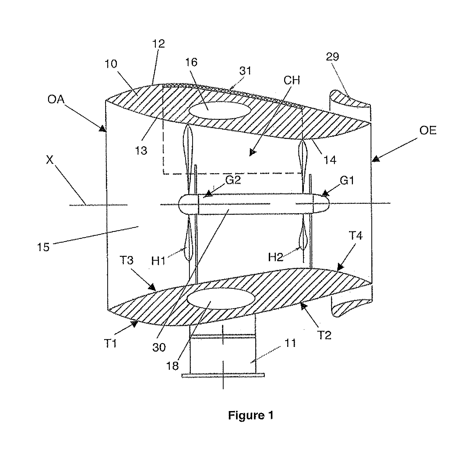
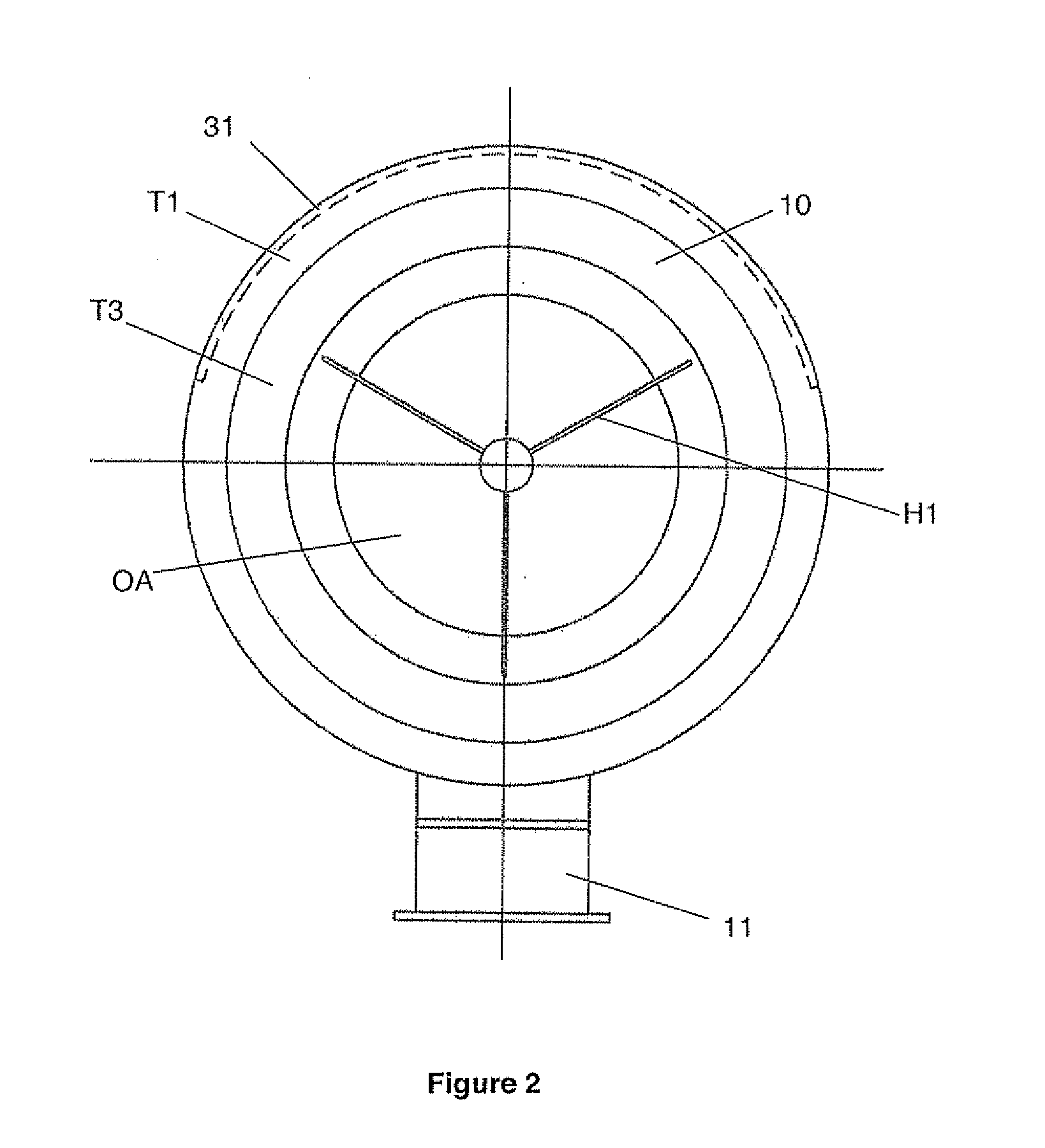
[0025]With reference to FIGS. 1 to 4, the example of a wind turbine according to the invention comprises a tubular casing 10 mounted with rotation along a vertical axis at the apex of a support structure 11. Tubular casing 10 presents a general revolution form and therefore has an axis of revolution which will correspond in the following to the air flow direction X, which is straight and horizontal. Orientation of tubular casing 10 with respect to support structure 11 is performed automatically, i.e. in free manner according to the direction of the wind, or by a directing mechanism ensuring that the air flow direction X is co-linear to the direction of the wind.

[0026]At one end (on the left in FIGS. 1, 3, 4), tubular casing 10 delineates an inlet opening OA of circular shape for inlet of air if there is any wind blowing. At the opposite end (the right in FIGS. 1, 3, 4), tubular casing 10 delineates an outlet opening OE of circular shape the diameter whereof can be slightly smaller t...


PUM


Abstract

A wind turbine comprises a tubular casing having an inlet opening, an outlet opening, an outer surface generating a pressure decrease, an inner surface presenting a convergent section joined to the inlet opening, a divergent section joined to the outlet opening and to the convergent section by a throat, and a propeller mounted rotating with respect to the tubular casing in proximity to the throat. It is coupled to a first generating machine. It comprises another propeller mounted rotating with respect to the tubular casing, placed upstream from the first propeller in the convergent section.

Description

BACKGROUND OF THE INVENTION[0001]The invention relates to a wind turbine having a tubular casing comprising:[0002]a circular air inlet opening,[0003]a circular outlet opening,[0004]an outer surface generating a pressure decrease, between the inlet opening and the outlet opening,[0005]an inner surface delineating an air passage joining said openings, having a horizontal straight direction of flow and presenting a convergent section joined to the inlet opening and a divergent section joined to the outlet opening, said sections being joined to one another by a throat,[0006]rotary means positioned axially in proximity to the throat and converting the air flow movement at the throat into a rotational movement of a coupling means connected to a first generating machine,[0007]and a first propeller mounted rotating with respect to the tubular casing, upstream from the rotary means, placed axially in the convergent section of the inner surface.STATE OF THE ART[0008]Such wind turbines are kno...

Claims


Application Information

Patent Timeline
IPC IPC(8): F03D1/02H02P9/04F03D1/04
CPCF03D1/025F03D1/04F05B2240/13Y02E10/72F05B2250/711F05B2250/712F05B2240/14Y02E70/30F03D9/255F03D9/11
Inventor CARRE, FREDERIC
Owner ELENA ENERGIE
Why Eureka
Try Eureka