Method for reinforcing a fibre composite component and a vacuum mat and arrangement for producing a reinforced fibre composite component

a technology of fibre composite components and vacuum mats, which is applied in the direction of applications, manufacturing tools, food shaping, etc., can solve the problems of time-consuming, component weight increase, and the wrapping process of components

Inactive Publication Date: 2010-12-16
AIRBUS OPERATIONS GMBH
View PDF4 Cites 20 Cited by
  • Summary
  • Abstract
  • Description
  • Claims
  • Application Information

AI Technical Summary

Benefits of technology

[0009]Against this background, the object of the present invention is to provide a method for reinforcing a fibre composite component as well as a vacuum

Problems solved by technology

The wrapping process of a component is carried out completely by hand which, particularly in the case of reinforcing elements, for example the above-mentioned stringers, is very time consuming, because the vacuum film has to be guided over these reinforcing elements while precisely following the contour thereof in order to prevent distortion of the component.
Due to the manual process management, the reproducibility suffers from considerable unreliability, such that for example for positioni

Method used


Image

  • Method for reinforcing a fibre composite component and a vacuum mat and arrangement for producing a reinforced fibre composite component
  • Method for reinforcing a fibre composite component and a vacuum mat and arrangement for producing a reinforced fibre composite component
  • Method for reinforcing a fibre composite component and a vacuum mat and arrangement for producing a reinforced fibre composite component

Examples


first embodiment

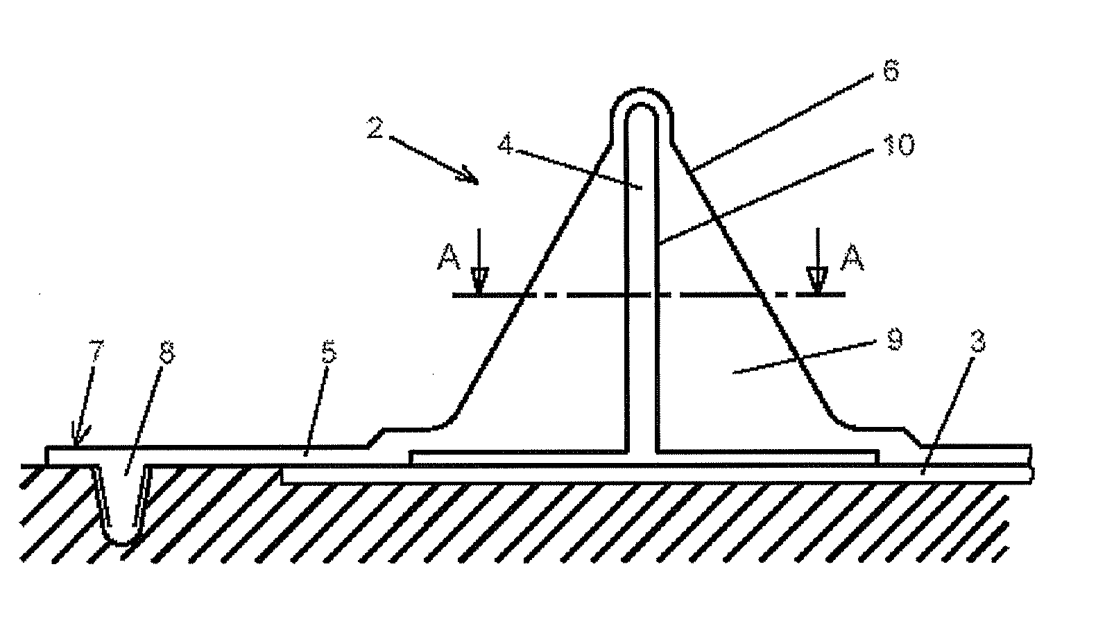
[0035]FIG. 1 is a schematic cross-sectional view of a mould portion 2 of a fibre composite component portion 3 of a fibre composite component 1 (see FIG. 3) with a vacuum mat 5 according to the invention with a receiving portion 6.

[0036]The fibre composite component portion 3 is arranged here on a base plate 24 of a production arrangement (see FIG. 9), which is described in more detail further below, and is provided for reinforcing by a reinforcing element 4, in this case a T-stringer by a vacuum infusion process in the illustrated mould portion 2.

[0037]For this purpose, the reinforcing element 4 was previously introduced in a different location into a recess 10, compatible with the reinforcing element 4, of the receiving portion 6 of the vacuum mat 5 and is completely enclosed by said recess 10. In this case, the vacuum mat 5 is produced from silicone. In the receiving portion 6, the silicone material as a receiving body 9 surrounds the reinforcing element 4. Before the fibre compo...

second embodiment

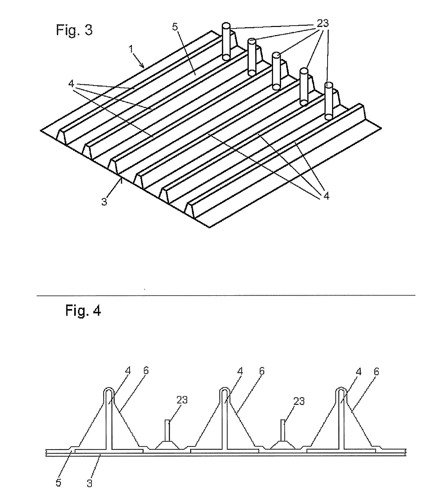
[0041]Only one reinforcing element 4 is shown in FIG. 1 and is described, but a plurality of reinforcing elements 4 can be required for reinforcing a fibre composite component 1, as FIG. 3 shows in a perspective plan view of an exemplary fibre composite component 1 with mould portions 2 with the vacuum mat 5 according to the invention.

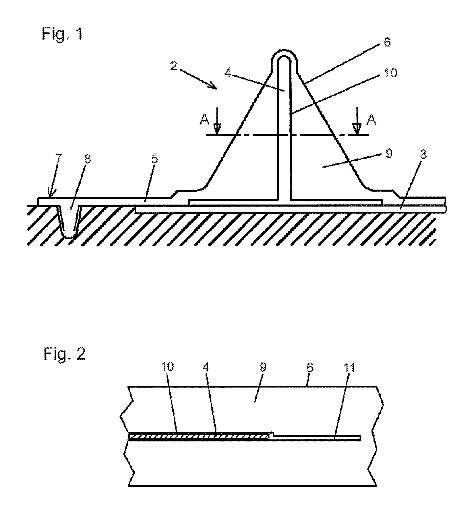
[0042]In FIG. 3, six reinforcing elements 4 are arranged on the fibre composite component portion 3 of the fibre composite component 1 and are covered by the vacuum mat 5 which, in this case, has a recess 10 for each reinforcing element 4. Furthermore, in this second embodiment, the vacuum mat 5 is fitted with closable air supply means 23, through which air or gas is blown in between the vacuum mat 5 and the fibre composite component portion 3 when the vacuum mat 5 is removed from the mould in order to facilitate the removal from the mould. In this respect, the incisions, show in FIG. 2, are widened by the air which is blown in and thus allow the recei...


PUM

PropertyMeasurementUnit
Stiffnessaaaaaaaaaa
Vacuumaaaaaaaaaa

Abstract

In a method for reinforcing a fibre composite component for aviation and space flight, a vacuum mat is configured with at least one receiving portion for reproducibly receiving at least one reinforcing element. The at least one reinforcing element is introduced into the at least one receiving portion of the vacuum mat. The vacuum mat with at least one introduced reinforcing element is applied reproducibly in a sealed manner to the fibre composite component to be reinforced to form a mould portion and at least the formed mould portion is cured to connect the at least one reinforcing element to the fibre composite component. The vacuum mat is then removed from the reinforced fibre composite component so that the vacuum mat can be reused.

Description

CROSS-REFERENCE TO RELATED APPLICATIONS[0001]This application is a continuation of PCT / EP2008 / 065699 and claims the benefit of U.S. Provisional Application No. 61 / 008,401, filed Dec. 20, 2007 and German Patent Application No. 10 2007 061 431.6, filed Dec. 20, 2007, the entire disclosures of which are herein incorporated by reference.FIELD OF THE INVENTION[0002]The present invention relates to a method for reinforcing a fibre composite component, in particular for aviation and space flight, and to a vacuum mat and an arrangement for producing a reinforced fibre composite component of this type.[0003]Although the present invention and the problem on which it is based can be applied to any fibre composite components, in the following they will be described in detail in respect of planar, stringer-reinforced carbon fibre plastics material (CFRP) components (also called fibre composite components), for example skin shells of an aircraft.[0004]It is generally known to reinforce CFRP skin ...

Claims


Application Information

Patent Timeline
IPC IPC(8): B32B37/10B65H29/00B65H43/00B29C48/76
CPCB29C33/405B29C33/46B29K2707/04B29C70/54B29K2063/00B29C70/443B29D99/0014
Inventor LUEBBERING, CHRISTIANLENGSFELD, HAUKEBRANDENBURG, ROLAND
Owner AIRBUS OPERATIONS GMBH
Why Eureka
Try Eureka