Three-Phase Brushless DC Motor

a three-phase, brushless dc motor technology, applied in the direction of horology, instruments, exposure control, etc., can solve the problems of high cost, high cost, and difficulty in making a big speed reduction ratio, so as to increase torque and reduce noise , the reduction ratio of the speed reducer connected to the motor is made low.

Inactive Publication Date: 2010-12-16
TAMRON
View PDF25 Cites 23 Cited by
  • Summary
  • Abstract
  • Description
  • Claims
  • Application Information

AI Technical Summary

Benefits of technology

[0023]The three-phase brushless DC motor according to the present invention can make the size of the rotor increase to obtain an increased torque even when the motor is installed in a site in which the installation space of the motor is restricted. As a result, even when reduction ratio of a speed reducer connected to the motor is made low, i.e. the motor can supply a sufficient torque with reduced noise generated in the speed reducer to make the motor silent and same time, accuracy in stop position of the motor can be improved also. In addition, as the motor is provided with the plurality of stator sections, it is excellent in making installation space free when compared to the conventional inner rotor-type three-phase brushless DC motor which is provided with a circular stator.

Problems solved by technology

However, the pulse motors (step motors) disclosed in Japanese Patent No. 2559827 and Japanese Patent Application No. 2005-57903 which provides a starting torque lower than the torque in a constant speed motion may fail quick start when high load is required.
However, as improvement in driving performance requires increased external size in the conventional three-phase brushless DC motor, an increase in the output power of the three-phase brushless DC motor installed in a limited installation space has been a challenge.
However, a speed reduction ratio is required to be made big because torque is low when the brush DC motor 100 is used.
As a result, a loud driving sound and a low transmission speed not suitable for quick response may arise as a problem to be solved.
So, it has been difficult to provide a high-torque three-phase brushless DC motor as a motor arranged in a limited space, for example, in the lens barrel.

Method used


Image

  • Three-Phase Brushless DC Motor
  • Three-Phase Brushless DC Motor
  • Three-Phase Brushless DC Motor

Examples


Embodiment Construction

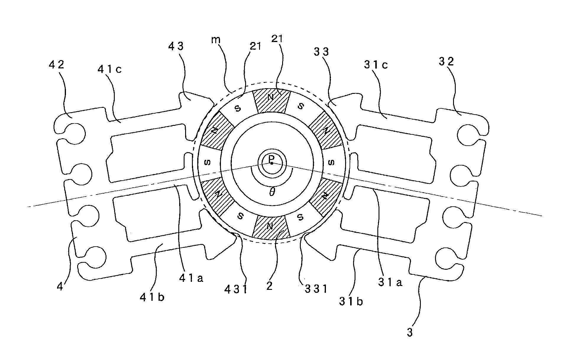
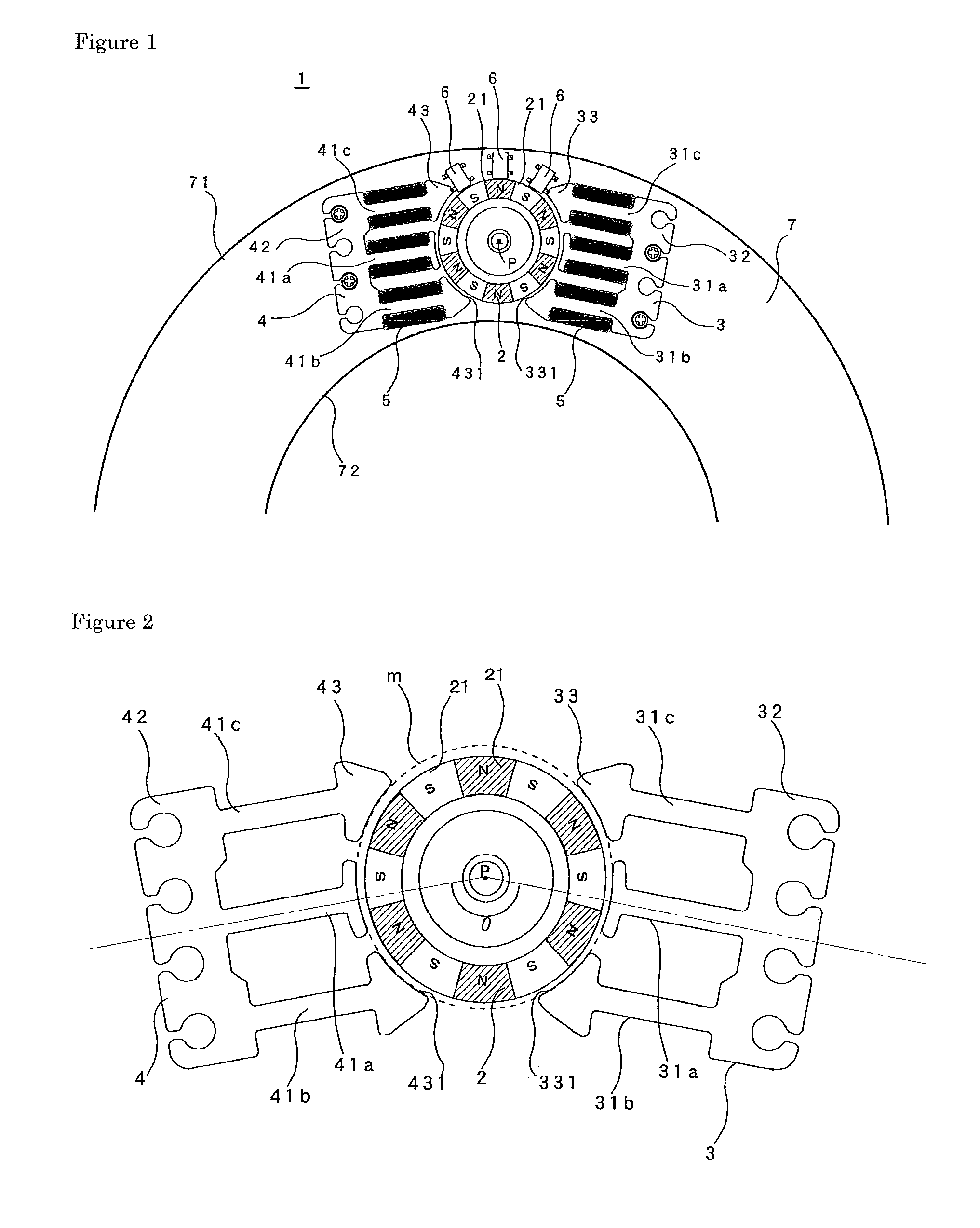
[0030]A preferred embodiment of a three-phase brushless DC motor according to the present invention will be described. FIG. 1 is a schematic diagram showing an example of an embodiment of the three-phase brushless DC motor according to the present invention arranged in a lens barrel in a camera seen in the direction of the axis of rotation of the rotor 2.

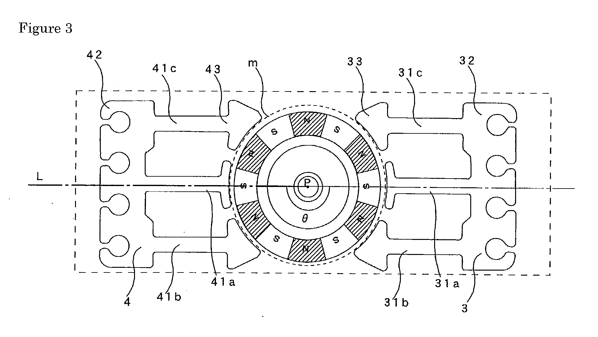
[0031]The three-phase brushless DC motor according to the present invention is an inner rotor-type three-phase brushless DC motor comprising a rotor provided with a plurality of magnetic poles divided equally in the center and a stator separately arranged along an outer peripheral side of the rotor.

[0032]The exemplified three-phase brushless DC motor 1 shown in FIG. 1 provided with a rotor 2, a stator composed of stator section 3 and the stator section 4, and a position detection sensor 6 set to detect the positions of magnetic poles 21 in the rotor 2 is the case installed in a lens barrel in an imaging device such as a camera. Two ...


PUM


Abstract

An object of the present invention is to provide a three-phase brushless DC motor providing a high torque and performs stable operations which can be used even when an installation space is restricted. To achieve the object, the present invention adopts an inner rotor-type three-phase brushless DC motor in which an inner rotor-type three-phase brushless DC motor comprising a rotor provided with a plurality of magnetic poles divided equally in a circumferential direction at an outer peripheral of the rotor and a stator separately arranged along an outer peripheral of the rotor, wherein the stator is provided with M−n (wherein, n is an integer equal to or larger than 1) of stator sections each provided with three stator poles each having different phases, and the relationship between number of magnetic poles provided in the rotor and the total number of stator poles is made different from the conventional one.

Description

TECHNICAL FIELD[0001]The present invention relates to an inner rotor-type three-phase brushless DC motor in which a rotor provided with a magnet is arranged at center side and a stator is arranged at outside of the rotor.BACKGROUND ART[0002]Various kinds of motor are used as driving sources for a lens moving mechanism for a zooming lens, a focusing lens, and the like in an optical devices such as a camera, a moving mechanism such as a diaphragm mechanism for brightness adjustment, and a moving mechanism provided in electrical products. For example, Japanese Patent No. 2559827 discloses an optical device using a pulse motor as a driving source for moving a movable lens or a diaphragm device for brightness adjustment.[0003]In recent years, effort has been made on size reduction, less power consumption and high performance for the optical devices and electrical products. Thus, the motor used for a driving source has been required not only improved performance, for example, the starting...

Claims


Application Information

Patent Timeline
Patent Type & Authority Applications(United States)
IPC IPC(8): H02K21/16
CPCG02B7/102H02K1/143H02K21/185H02K29/03
Inventor SHIGA, NAOTO
Owner TAMRON
Why Eureka
Try Eureka