Method And Apparatus For Compressive Imaging Device Having Startle Reflex

a compression imaging and startle reflex technology, applied in the field of imaging devices, can solve the problems of missing an important event entirely, reducing the computational complexity of the video encoding process, and acquiring large amounts of raw image or video data (large n)

Inactive Publication Date: 2010-12-16
RICE UNIV
View PDF19 Cites 9 Cited by
  • Summary
  • Abstract
  • Description
  • Claims
  • Application Information

AI Technical Summary

Benefits of technology

[0014]A small number of detectors, even a single detector, can be used. Thus, the camera can be adapted to image at wavelengths of electromagnetic radiation that are currently impossible with conventional CCD and CMOS imagers. This feature is particularly advantageous, because in some cases the usage of many detectors is impossible or impractical, whereas the usage of a small number of detectors, or even a single detector, may become feasible using compressive imaging.
[0015]A camera in accordance with the present invention can also be used to take streaming measurements of a video signal, which can then be recovered using CS techniques designed for either 2-dimensional (2D) frame-by-frame reconstruction or joint 3D reconstruction. This allows a significant reduction in the computational complexity of the video encoding process.
[0017]Potentially single detector or small number of detectors: By time-multiplexing each detector, we can use a less expensive and yet more sensitive photon detectors. This is particularly important when the detector is expensive, making an N-pixel array prohibitive. A single detector camera can also be adapted to image at wavelengths that are currently impossible with conventional CCD and CMOS imagers.
[0020]Robustness and progressivity: Random and pseudorandom measurements are robust in the sense that the measurements have equal priority, unlike the Fourier or wavelet coefficients in current transform coders. Thus they allow a progressively better reconstruction of the data as more measurements are obtained; one or more measurements can also be lost without corrupting the entire reconstruction.

Problems solved by technology

First, acquiring large amounts of raw image or video data (large N) can be expensive, particularly at wavelengths where CMOS or CCD sensing technology is limited.
Second, compressing raw data can be computationally demanding, particularly in the case of video.
In the former case, scheduled power-off periods could result in missing an important event entirely.
In the latter case, we require additional hardware that may be costly or undesirable.
Moreover, in both cases the system suffers from a “power-on lag,” which delays image or video capture, potentially causing the camera to miss the important event.
This kind of scheme is impossible in the traditional digital camera paradigm, which is an all-or-nothing scheme: either an image / video is captured at full rate, or no image / video is captured at all.

Method used


Image

  • Method And Apparatus For Compressive Imaging Device Having Startle Reflex
  • Method And Apparatus For Compressive Imaging Device Having Startle Reflex
  • Method And Apparatus For Compressive Imaging Device Having Startle Reflex

Examples


example 1

Still Image Acquisition

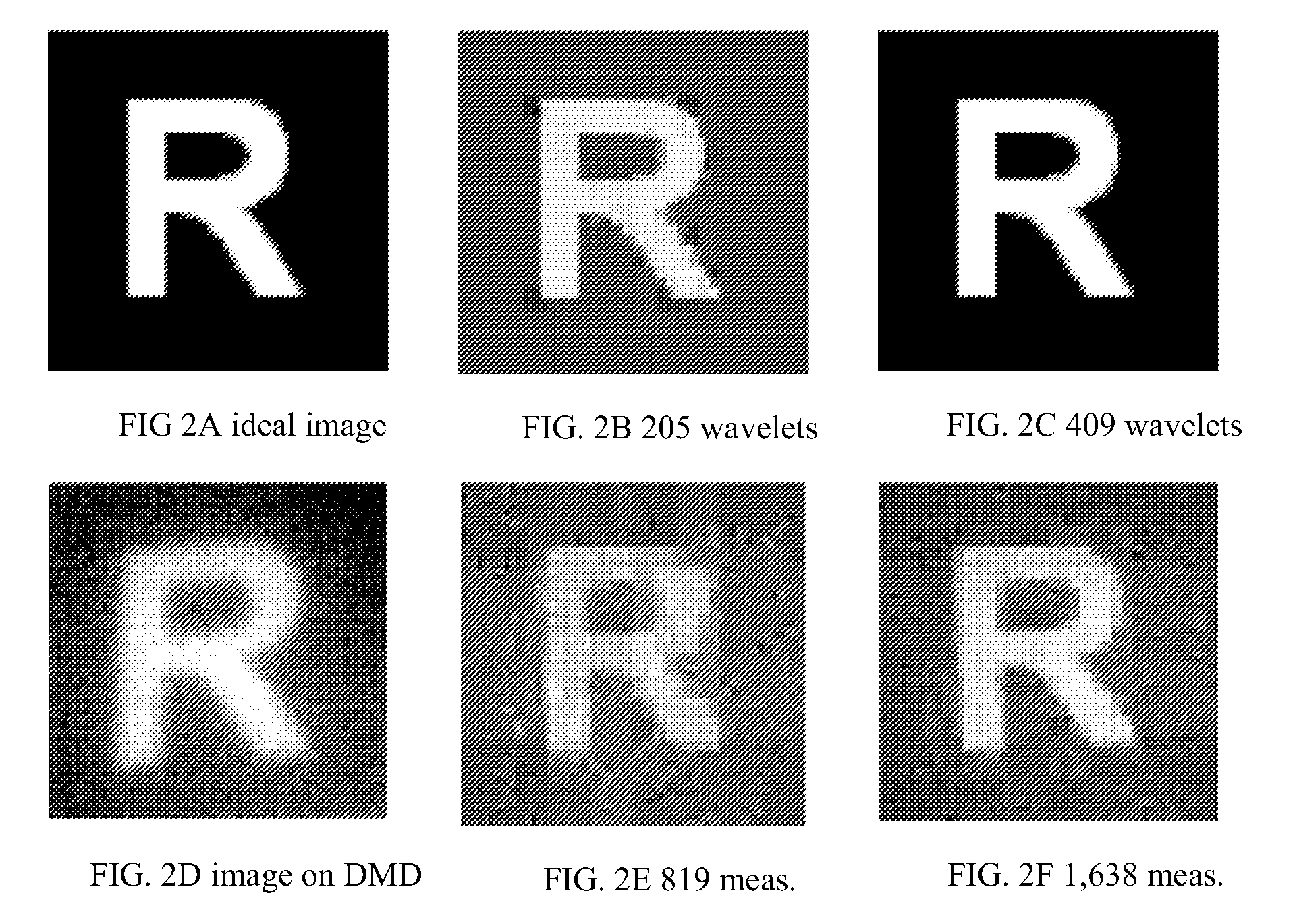
[0071]For an imaging experiment, we displayed a printout of the letter “R” in front of the camera; FIG. 2A shows the printout. For acquisition and reconstruction, we use an imaging resolution of N=64×64=4096. Since our test image is piecewise constant (with sharp edges) it can be sparsely represented in the wavelet domain. FIGS. 2B and 2C show the best K-term Haar wavelet approximation of the idealized image in FIG. 2A with K=205 and 409, respectively. Using M=819 and 1,638 measurements (roughly 4× the K used in B and C), we reconstructed the images shown in FIGS. 2E and 2F using the Dantzig Selector (see Candès, E., Tao, T., “The Dantzig selector: Statistical estimation when p is much larger than n,” (2005) Preprint), a robust scheme for CS reconstruction. In all cases Haar wavelets were used for approximation or reconstruction. This preliminary embodiment confirms the feasibility of the CI approach; resolution of minor calibration and noise issues will impro...

example 2

Video Simulation

[0072]To demonstrate the potential for applications in video encoding, we present a series of simulations for video measurement / reconstruction. Column (a) in FIG. 3 shows a single frame taken from our F=64 frame video sequence that consists of P=64×64 images; in total the video contains N=FP=262,144 3D voxels. The video shows a disk moving from top to bottom and growing from small to large. We measure this video sequence using a total of M measurements, either 2D random measurements (with M / F measurements / frame) or 3D random measurements. (For the 2D measurements, we make the simplifying assumption that the image remains constant across all snapshots within a given frame.) To reconstruct the video from these measurements we compare two approaches: 2D frame-by-frame reconstruction using 2D wavelets as a sparsity-inducing basis and 3D joint reconstruction using 3D wavelets as a sparsity-inducing basis.

[0073]FIG. 3 shows Matching Pursuit reconstruction results using M=2...


PUM


Abstract

A method and apparatus for new digital image / video camera that directly acquires random projections of the incident light field without first collecting the pixels / voxels and has a startle reflex. The startle reflex is achieved by collecting a training set of samples while operating the imaging device at the low sampling rate, computing an empirical probability distribution of the training set of samples, collecting a testing set of samples while operating the imaging device at the low sampling rate, computing an empirical probability distribution of the testing set of samples, computing an empirical entropy test statistic, and capturing an image at the high sampling rate in response to the computed empirical entropy statistic exceeding a threshold.

Description

CROSS-REFERENCE TO RELATED APPLICATIONS[0001]The present application is a continuation of U.S. Nonprovisional patent application Ser. No. 11 / 379,688, filed on Apr. 21, 2006, which claimed the benefit of the filing dates of U.S. Provisional Application Ser. No. 60 / 673,364 entitled “Method and Apparatus for Optical Image Compression,” and filed on Apr. 21, 2005; U.S. Provisional Application Ser. No. 60 / 679,237 entitled “Method and Apparatus for Reconstructing Data from Multiple Sources,” and filed on May 10, 2005; U.S. Provisional Application Ser. No. 60 / 729,983 entitled “Random Filters for Compressive Sampling and Reconstruction,” and filed on Oct. 25, 2005; U.S. Provisional. Application Ser. No. 60 / 732,374 entitled “Method and Apparatus for Compressive Sensing for Analog-to-Information Conversion,” and filed on Nov. 1, 2005; U.S. Provisional Application Ser. No. 60 / 735,616 entitled “Method and Apparatus for Distributed Compressed Sensing,” and filed on Nov. 10, 2005; and U.S. Provis...

Claims


Application Information

Patent Timeline
Patent Type & Authority Applications(United States)
IPC IPC(8): H04N17/00
CPCH04L25/20H04N3/08H04N5/335H04N25/00
Inventor GOODMAN, ILAN N.JOHNSON, DON H.BARANIUK, RICHARD G.KELLY, KEVIN F.
Owner RICE UNIV
Why Eureka
Try Eureka