Plasmon antenna with magnetic core for thermally assisted magnetic recording

Active Publication Date: 2010-12-16
HEADWAY TECH INC
View PDF10 Cites 45 Cited by
  • Summary
  • Abstract
  • Description
  • Claims
  • Application Information

AI Technical Summary

Benefits of technology

[0019]It is a first object of the present invention to produce a new TAMR antenna structure in which the simultaneous application of magnetic field and heat to a heating spot on a magnetic medium is optimized to produce a greater effective recording field gradient.
[0020]It is a second object of this invention to achieve higher recording density on magnetic recording media by means of the improved TAMR scheme that utilizes the optimal positioning of the magnetic recording field and the thermal energy for heating the medium.
[0025]These objects will be achieved by means of a plasmon antenna design in which there is a core of magnetic material, such as CoFe or NiFe, overcoated with a non-magnetic highly conductive metal, such as Au or Ag. This proposed antenna composition, with its central magnetic core and with edge plasmon mode excitation resulting from radiative coupling to an optical waveguide substantially confined to the overcoat, will self align the magnetic field gradient with a thermal heating gradient produced by the plasmon mode during magnetic recording. This self-alignment, in which maximum thermal gradients and maximum magnetic field gradients are aligned, will enhance the effective recording field gradient and achieve higher recording density. The fabrication method is easily adaptable to existing head fabrication techniques. By attaching the antenna directly to the writer pole, as in one of the preferred embodiments, the fabrication method can be further simplified and an additional benefit of lower antenna temperature during operation can be achieved.

Problems solved by technology

Satisfying these requirements simultaneously may be a limiting factor in the further development of the present magnetic recording scheme used in state of the art hard-disk-drives (HDD).
If that is the case, further increases in recording area density may not be achievable within those schemes.
However, in the prior art a problem still exists in aligning the optical heating profile within the region of energy transfer at the medium surface, with the magnetic field profile generated by the write head.
Although this location will allow sufficient writing resolution with enough heating, it is not the optimal positioning of the two curves relative to each other.
Due to structural limitations, caused, for example, by the thickness and arrangement of the WG and by choice of the PA design, difficulties in alignments during fabrication, etc., optimal alignment of the heating and field profiles cannot be obtained.

Method used


Image

  • Plasmon antenna with magnetic core for thermally assisted magnetic recording
  • Plasmon antenna with magnetic core for thermally assisted magnetic recording
  • Plasmon antenna with magnetic core for thermally assisted magnetic recording

Examples


embodiment 1

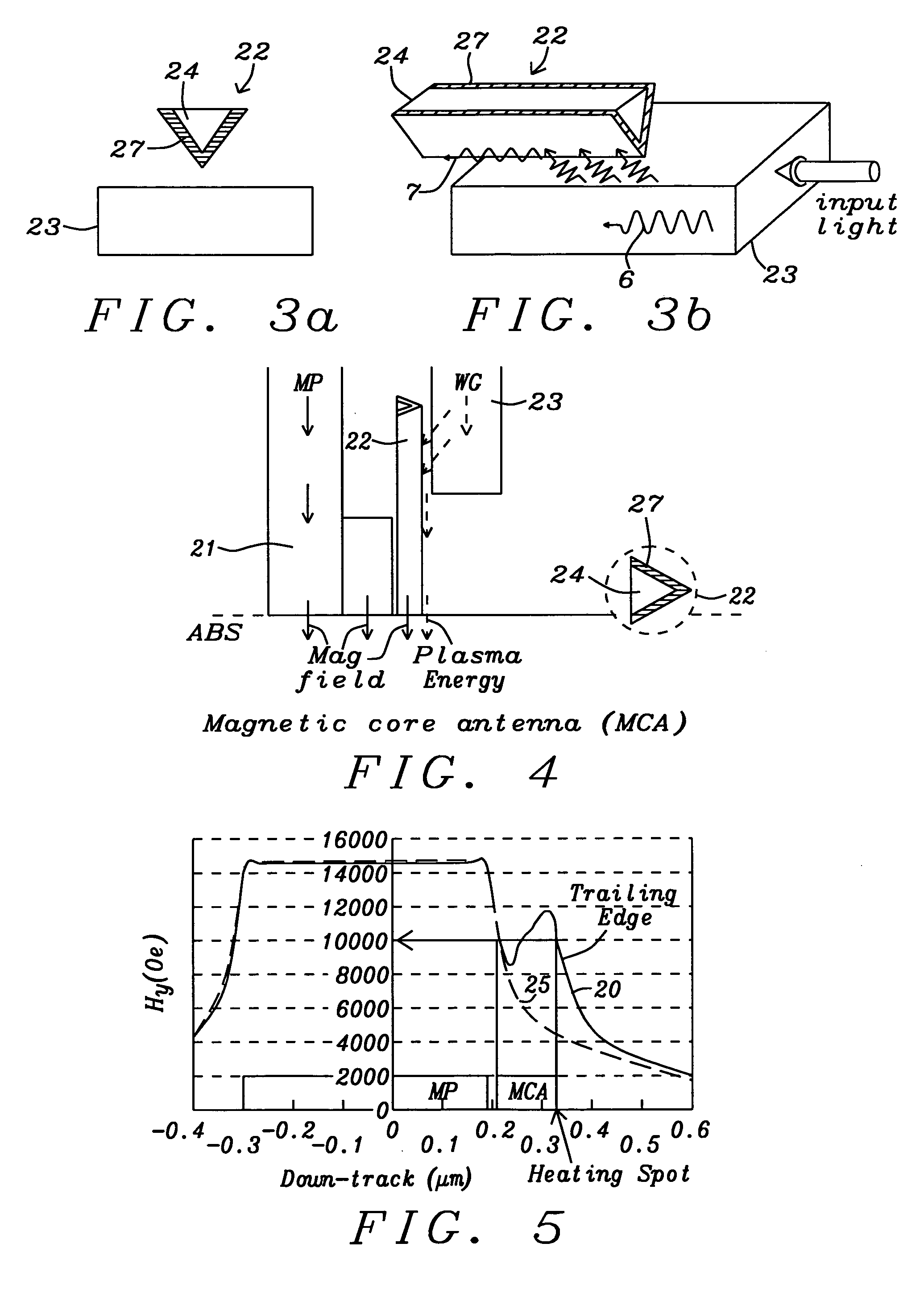
[0058]Referring to schematic FIG. 8a, there is shown a side view of a first embodiment of a TAMR head that has a magnetic write pole (21), a plasmon antenna (22) and an optical waveguide (23). The magnetic pole generates a magnetic field to switch the magnetizations of medium grains during the recording process. The plasmon antenna (22) transmits electromagnetic energy from an edge plasmon mode to the medium. The plasmon mode is, in turn, generated, by optical radiation within the waveguide (23) that couples to the plasmon generating layer ((27) in FIG. 8b) of the plasmon antenna. The electromagnetic energy of the plasmon mode produces localized heating of the medium through absorption of electric field energy from the plasmon mode by the medium. The heating reduces medium anisotropy and coercivity to enable an easier switching by the magnetic field emanating from (21) and from (22).

[0059]More specifically, the waveguide (23) transmits an externally generated optical frequency elect...

embodiment 2

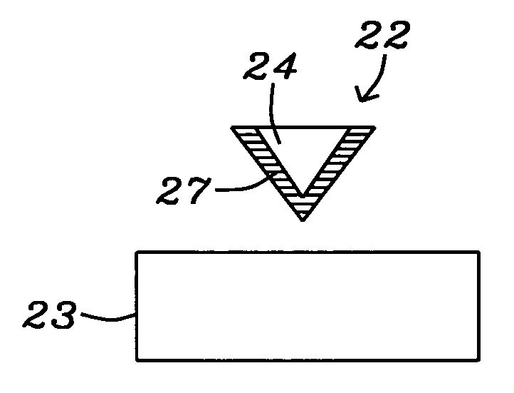
[0066]Referring to FIG. 9a, there is shown a schematic side view of a second embodiment of the plasmon antenna of the present invention which is similar to the first embodiment except that the plasmon antenna (22) is neither physically a part of nor is it directly attached to the writer magnetic pole (21). Instead, a non-magnetic separation layer (28) (shown as a space), metallic or non-metallic, separates the base of the antenna and the trailing edge surface of the write pole. Referring to schematic FIG. 9b, there is shown a horizontal cross-sectional view looking up at the ABS of the structure of FIG. 9a from the medium surface, showing the same elements. The distal surface of the waveguide (23) is shown as dashed, to indicate that it is recessed from the ABS, The plasmon antenna (22) is shown with its core (24) and plasmon generating layer (27) visible.

[0067]As is shown in FIG. 9c, the first step in fabricating the structure of FIG. 9a, is the deposition of a magnetic core layer ...

embodiment 3

[0068]Referring to schematic FIG. 10a, there is shown a side view of a third embodiment of the plasmon antenna (22) which functions in generally the same manner as the first two embodiments. In this embodiment, however, the waveguide (23) positioned partially between the write pole (21) and the antenna (22). The write pole (21) is, therefore, given an L shape to accommodate the placement of the waveguide (23). The ABS of the pole is shown with a slight extension.

[0069]Referring to FIG. 10b, there is shown a horizontal cross-sectional view of the same configuration from an upward facing perspective. The outline of the waveguide (23) is dashed, to indicate that it is not in the same plane as the other features. The entire L shaped base of the pole is not fully illustrated.

[0070]Because of the positioning of the waveguide relative to the antenna, the coupling of the optical mode to the plasmon mode will be through the exposed edges of the metallic layer (27), rather than at the vertex ...


PUM

PropertyMeasurementUnit
Lengthaaaaaaaaaa
Lengthaaaaaaaaaa
Lengthaaaaaaaaaa

Abstract

A TAMR (Thermal Assisted Magnetic Recording) write head uses the energy of optical-laser generated plasmons in a plasmon antenna to locally heat a magnetic recording medium and reduce its coercivity and magnetic anisotropy. To enable the TAMR head to operate most effectively, the maximum gradient of the magnetic recording field should be concentrated in the small region being heated. Typically this does not occur because the spot being heated by the antenna is offset from the position at which the magnetic pole concentrates its magnetic field. The present invention incorporates a magnetic core within a plasmon antenna, so the antenna effectively becomes an extension of the magnetic pole and produces a magnetic field whose maximum gradient overlaps the region being heated by edge plasmons being generated in a conducting layer surrounding the antenna's magnetic core.

Description

BACKGROUND OF THE INVENTION[0001]1. Field of the Invention[0002]This invention relates to the fabrication of magnetic read / write heads that employ TAMR (thermally assisted magnetic recording) to enable writing on magnetic media having high coercivity and high magnetic anisotropy. More particularly, it relates to the use of a plasmon antenna (PA) to transfer the required thermal energy from the read / write head to the media.[0003]2. Description of the Related Art[0004]Magnetic recording at area data densities of between 1 and 10 Tera-bits per in2 (Tbpsi) involves the development of new magnetic recording mediums, new magnetic recording heads and, most importantly, a new magnetic recording scheme that can delay the onset of the so-called “superparamagnetic” effect. This effect is the thermal instability of the extremely small regions on which information must be recorded, in order to achieve the required data densities. A way of circumventing this thermal instability is to use magnetic...

Claims


Application Information

Patent Timeline
IPC IPC(8): G11B5/02
CPCG11B5/02G11B5/3116G11B5/314G11B5/3146G11B5/6088G11B2005/0005G11B2005/0021Y10T29/49032
Inventor ZHOU, YUCHENTAKANO, KENICHIJIN, XUHUISCHRECK, ERHARDDOVEK, MORISSMYTH, JOE
Owner HEADWAY TECH INC
Why Eureka
Try Eureka