Omni-directional fan device

a fan device and omni-directional technology, applied in the direction of wind motors, wind motor components, non-positive displacement fluid engines, etc., to achieve the effect of reducing the strain on the base structure, reducing the breakage of the fan head, and easy adjustmen

Active Publication Date: 2010-12-16
BAIN NORIAL P
View PDF9 Cites 15 Cited by
  • Summary
  • Abstract
  • Description
  • Claims
  • Application Information

AI Technical Summary

Benefits of technology

[0015]An advantage of the present invention is that it allows a fan's head or a vent associated with a fan to be easily adjusted in any direction without the strain of having to reposition the entire fan in order to feel the air flow, for example, by controlling an associated motor at a swivel point. By swivel point is intended a point of attachment to an air flow device such that the air flow device is practically unlimited in its range of motion about the swivel point such that air flow may be directed in a direction chosen within a sphere about the swivel point. A limitation on a plurality of directions of air flow may be a pole upon which the air flow device is mounted and the volume consumed by the air flow device such as a fan having a rotating blade. In some embodiments, two or more swivel points may be provided, for example, for a vent system to adjust tilt and twist of the air flow direction as well as to adjust circular direction.
[0016]Another advantage of the present invention is that breakage of a fan's head is significantly reduced because of the corresponding reduction of strain on the base structure of conventional electric fans and the increase in the flexibility of the fan's head in an aspect.
[0017]Yet another advantage of the present invention is that it provides a more user-friendly experience through ease of usability, enhanced product control including environmental sensors and user programmable air flow rate and direction control.
[0018]Yet another advantage of the present invention is to allow improved compliance with increasingly stricter air quality standards established or recommended for workplace and home environments. Moreover, an embodiment is disclosed which may conserve energy or may shut down upon inference of a safety concern.
[0019]In order to accomplish these and other advantages, an omni-directional fan device may comprise a programmable microprocessor controller and memory for storage of environmental data such as temperature and wind velocity, fan motor data such as rotational velocity, fan position data such as latitude and longitude data for representing location parameters for controlling movement at first and, if provided, second (and third) swivel points and user input data such as desired fan or vent directional movement and fan motor speed (i.e. rotational velocity) during fan movement. The omni-directional fan may comprise a remote control device for transmitting user input data by wired or wireless means for remotely programming the fan controller. Moreover, certain data such as environmental temperature and humidity data may be sensed at the fan by on-board sensors or remotely transmitted from remote sensor(s) thereof to the fan controller for periodically updating such data in memory. The temperature and humidity data may be used to calculate a known comfort index value and the comfort index value, in turn, used by the programmed controller to selectively adjust fan speed and direction. Moreover, the controller may control any associated humidifier output according to comfort index. In this manner, the fan or vent system for a fan of an air conditioner or heater or stand-alone fan may adapt its air flow direction and velocity to suit sensed environmental conditions. In some embodiments, the fan or vent system may be used in known air conditioning and heating systems for automatic air flow direction and air velocity control and the processor may react to an shut down the fan upon inferring a safety event.
[0020]Further features and advantages of the present invention, as well as the structure and operation of various aspects of the present invention, are described in detail below with reference to the accompanying drawings.

Problems solved by technology

A limitation on a plurality of directions of air flow may be a pole upon which the air flow device is mounted and the volume consumed by the air flow device such as a fan having a rotating blade.

Method used


Image

  • Omni-directional fan device
  • Omni-directional fan device
  • Omni-directional fan device

Examples


Embodiment Construction

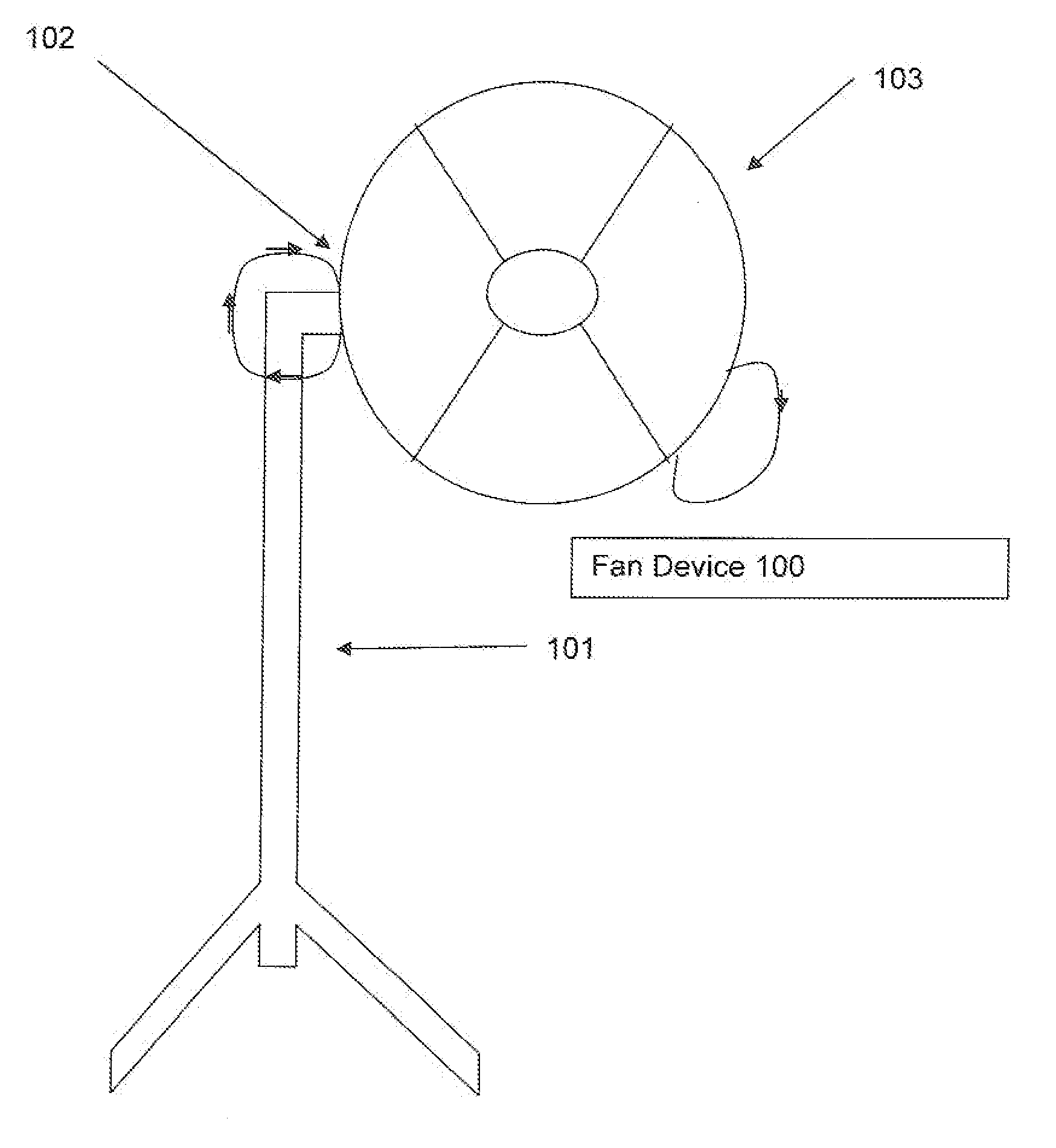
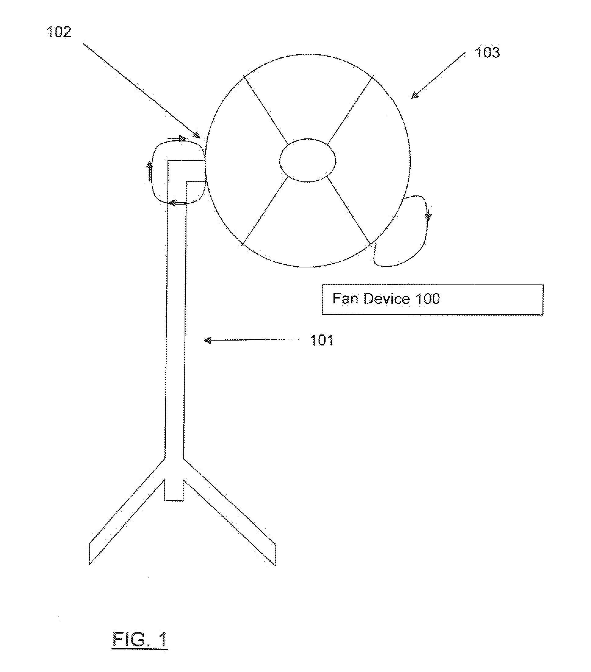
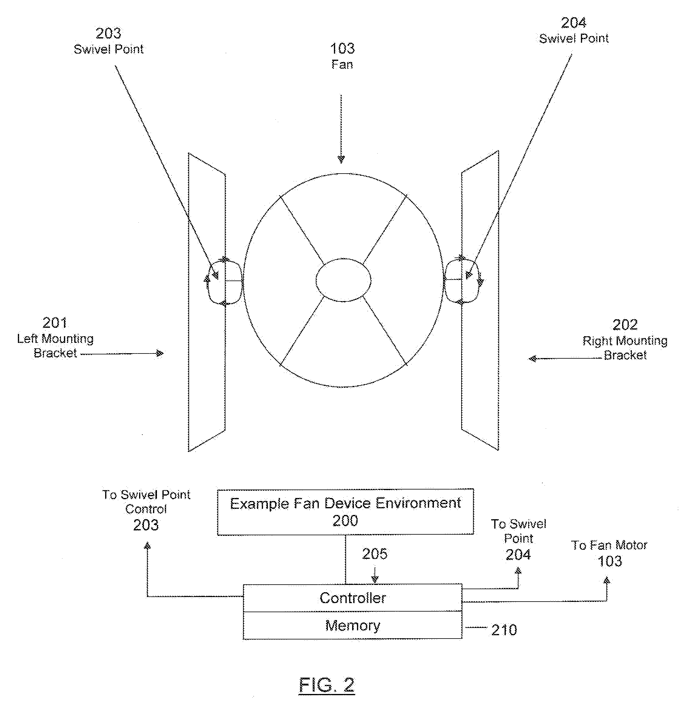
[0026]The present invention is directed to an air flow control device that allows a fan to rotate in any direction and so control air flow in a plurality of directions as well as air flow velocity as will be described further with reference to FIGS. 1, 2 and 3.

[0027]FIG. 1 presents an exemplary air flow device, for example, a fan device 100 comprising various well-known hardware components and other features in accordance with an aspect of the present invention. This is for convenience only and is not intended to limit the application of the present invention. In fact, after reading the following description, it will be apparent to those skilled in the relevant art(s) how to implement the following invention in alternative aspects.

[0028]In an aspect, a fan device 100 includes a floor-mounted omni-directional fan device and is mounted on a floor stand 101. The fan device 100 may be associated with an air conditioner, not shown, or a heating system which may be localized or central (f...


PUM


Abstract

An omni-directional air flow device, for example, a fan or a vent associated with a fan, comprises a swivel control point providing almost a spherical range of motion of the air flow device so that air may flow in any direction. The omni-directional air flow device may comprise a user input device for receiving a program for controlling movement of the air flow device through a pre-determined path within the spherical range of motion and for controlling air flow velocity as the air flow device follows the pre-determined path. Moreover, the device may further comprise a controller and memory for storing data representing the pre-determined path and varying air flow velocities along the path. When provided with temperature and humidity sensors coupled to the processor, the processor may calculate a comfort index and adjust the pre-determined path or air flow velocity accordingly. Links between the sensors and the processor, the swivel point and the processor and the user input device and the processor may be wireless.

Description

[0001]This application claims priority to provisional U.S. Patent Application Ser. No. 61 / 187,010, filed Jun. 15, 2009, the entire disclosure of which is hereby incorporated by reference into the present application.BACKGROUND OF THE INVENTION[0002]1. Field of the Invention[0003]The present invention generally relates to devices designed to accelerate volumes of air from one location to another, with the purpose of imparting a cooling effect and, more particularly, to an omni-directional air flow device that is user programmable and is adaptive to the environment. Examples of air flow devices include fans, air-conditioners, heating units and directional air flow vents associated therewith.[0004]2. Background[0005]People have used fans to keep cool for a long time. Initially, before the advent of electric and other motors, fans were either self-operated or operated by other people, such as servants. When electric motors became practical, fans powered by these motors came to be availa...

Claims


Application Information

Patent Timeline
Patent Type & Authority Applications(United States)
IPC IPC(8): F03D11/00
CPCF04D25/105
Inventor BAIN, NORIAL P.
Owner BAIN NORIAL P
Why Eureka
Try Eureka