Amphibious Robotic Crawler

a robotic crawler and amphibious technology, applied in underwater equipment, underwater equipment, vessel construction, etc., can solve the problems of unmanned ground vehicles that are not easy to operate, unmanned ground vehicles face many challenges, and vehicles optimized for operation in one environment may perform poorly in other environments, and achieve the effect of improving mobility

Active Publication Date: 2010-12-16
SARCOS LC
View PDF103 Cites 35 Cited by
  • Summary
  • Abstract
  • Description
  • Claims
  • Application Information

AI Technical Summary

Benefits of technology

[0009]The present invention includes an amphibious robotic crawler which helps to overcome the problems and deficiencies inherent in the prior art. In one embodiment, the amphibious robotic crawler includes a first frame and a second frame, with each frame having a continuous track rotatably supported therein and coupled to a drive mechanism through a drive unit. The frames are positioned end-to-end, and coupled with an active, actuated, multi-degree of freedom linkage. Buoyancy control elements are disposed on the frames to allow the crawler to operate either at the surface of the water or submerged. Propulsion is provided by the engagement of the continuous tracks with the water, while direction and attitude is controlled by bending or twisting the actuated linkage arm to position the first and second frames at an angle with respect to each other, which causes the crawler to turn, pitch or roll as it travels through the water. The continuous tracks can further be configured with a propulsive-enhancing tread which provides an asymmetric thrust between the top and bottom surfaces of the tracks, to provide enhanced mobility while traveling through the water.

Problems solved by technology

Less success has been achieved with unmanned ground vehicles (UGVs), however, in part because the ground or surface environment is significantly more variable and difficult to traverse than the airborne environment.
Unmanned ground vehicles face many challenges when attempting mobility.
A vehicle optimized for operation in one environment may perform poorly in other environments.
There are also tradeoffs associated with the size of vehicle.
On the other hand, large vehicles cannot easily negotiate narrow passages or crawl inside small spaces, such as pipes, and are more easily deterred by vegetation.
Large vehicles also tend to be more readily spotted, and thus are less desirable for discrete surveillance applications.
In contrast, while small vehicles are more discrete, surmounting obstacles becomes a greater mobility challenge.
Legged robots can be agile, but use complex control mechanisms to move and achieve stability and cannot traverse deep water obstacles.
Wheeled vehicles can provide high mobility on land, but limited propulsive capability in the water.
Robots configured for aquatic environments can use propellers or articulating fin-like appendages to move through water, but which may be unsuitable for locomotion on dry land.
Options for amphibious robots configured for both land and water environments are limited.
Robots can use water tight, land-based mobility systems and remain limited to shallow bodies of water.
They can also be equipped with both land and water mobility devices, such as a set of wheels plus a propeller and rudder, but this adds to the weight, complexity and expense of the robot.
However, the ground-configured dual tracks which are effective in propelling and turning the vehicle on the ground can provide only a limited degree of propulsion through water, and the vehicle's power system must often be over-sized in order to generate an acceptable amount of thrust when traveling in amphibious mode.
Furthermore, the differential motion between the two treaded tracks cannot provide the vehicle with the same level of maneuverability and control in water as it does on land, dictating that additional control structures, such as a rudder, also be added to the vehicle for amphibious operations.
Another drawback is that typical tracked amphibious vehicles also cannot operate submerged.

Method used


Image

  • Amphibious Robotic Crawler
  • Amphibious Robotic Crawler
  • Amphibious Robotic Crawler

Examples


embodiment 12

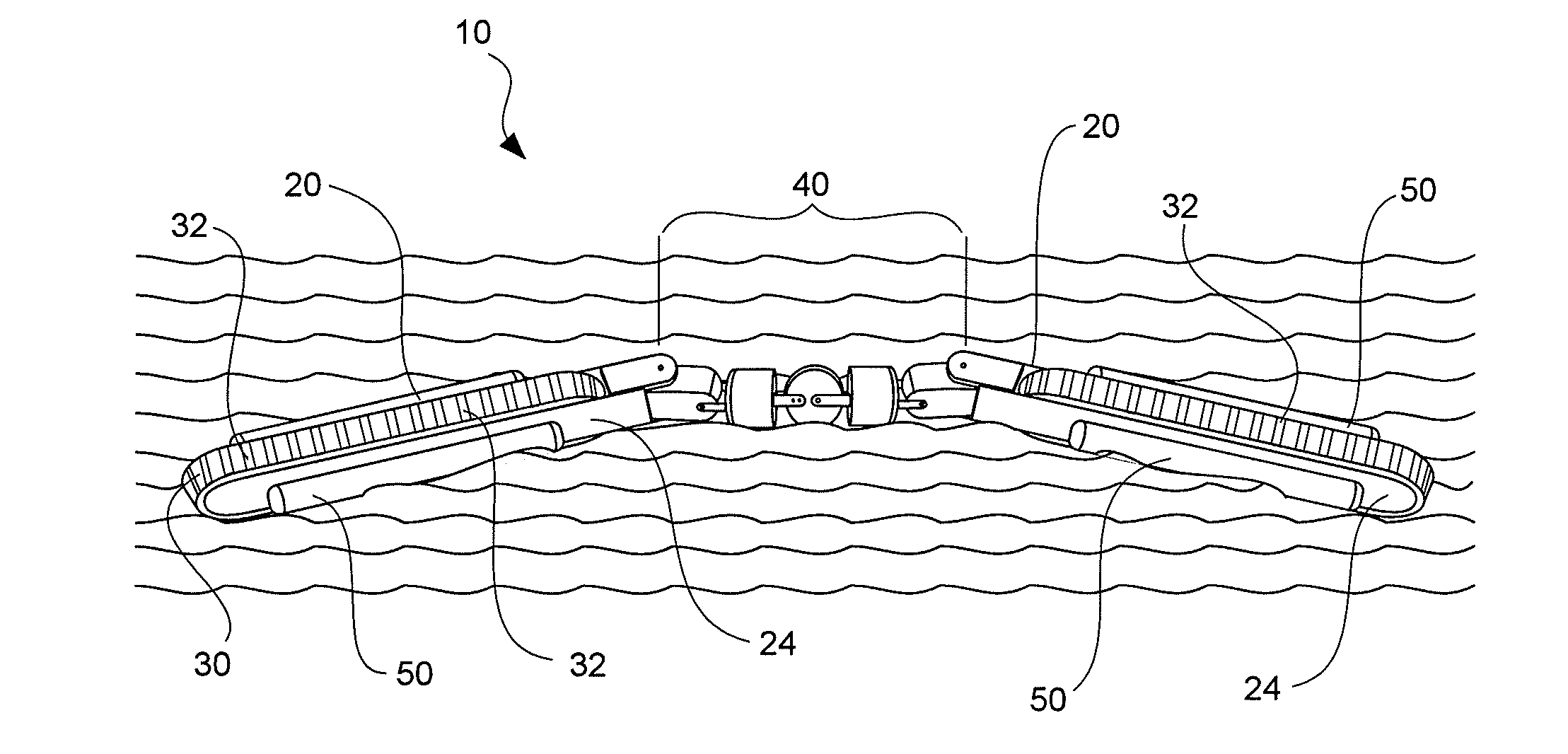
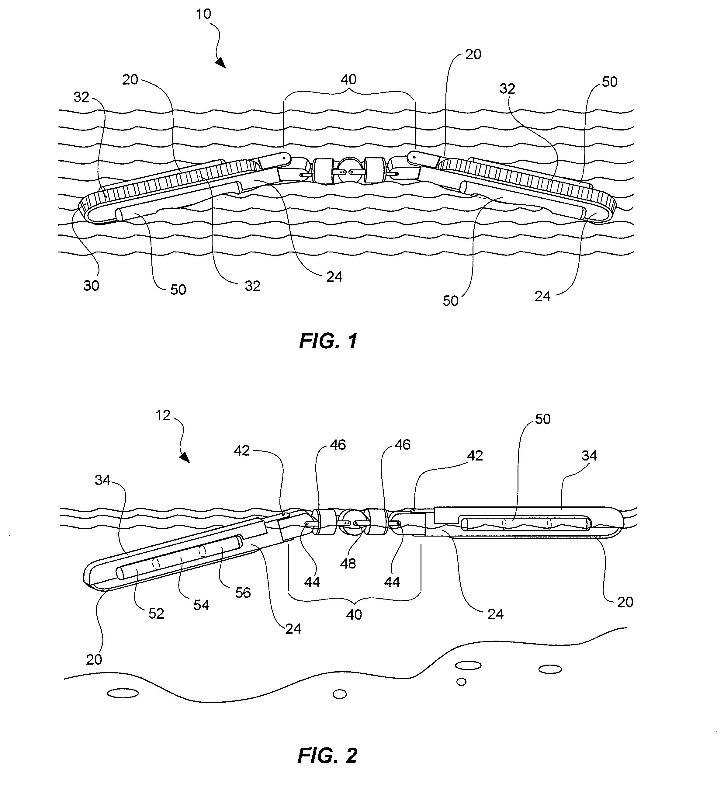
[0040]In the embodiment 12 of the present invention illustrated in FIG. 2, one surface of the continuous track 30 can be covered with a shield 34 that prevents the water from contacting the covered section of the continuous track while selectively permitting the uncovered section to substantially engage the water. The shield 34 can also be a mission configurable option that is removably attached to the housing 24 of the frame unit 20 before introducing the crawler 10 into the amphibious environment, and can be discarded after the crawler transitions from water to land to facilitate greater maneuverability of the crawler as it subsequently traverses ground terrain and obstacles.

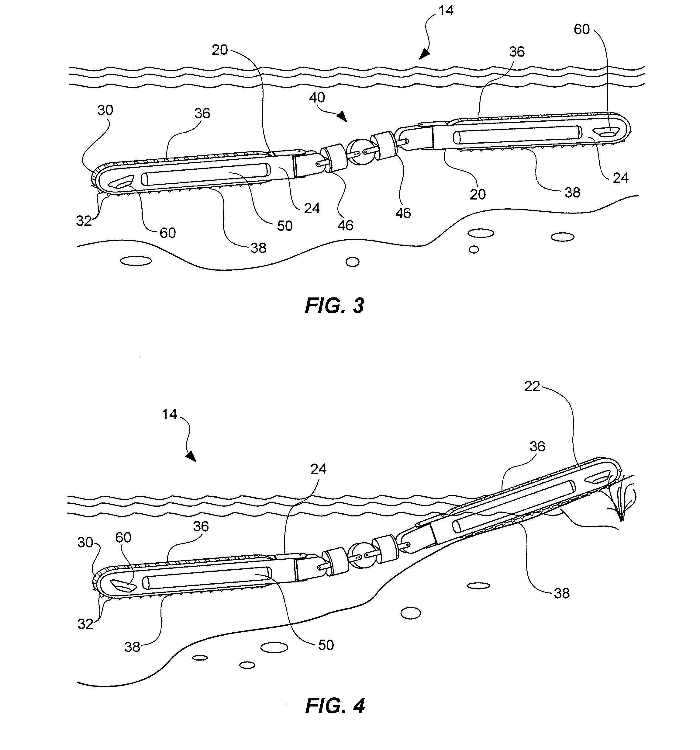
[0041]In another embodiment 14 of the present invention exemplified in FIGS. 3 and 4, the continuous track 30 can be provided with an asymmetric propulsion-enhancing tread which can provide an asymmetric thrust between the top and bottom surfaces of the tracks, to increase the mobility of the amphibious roboti...

embodiment 18

[0048]In another representative embodiment 18 illustrated in FIG. 6, the amphibious robotic crawler can be provided with an auxiliary thrust or propulsion module 70, such as a propeller system or water jet, etc. The auxiliary thrust system can be mounted into a thrust pod 72 supported on actuatable arms 74 deployed from a frame unit 20, which arms can rotated upward to a raised position to lift the thrust pod above the crawler as it moves over the ground. The arms can then rotate downwards during water operations to locate the thrust pod in a optimal orientation for propelling the crawler through the water. Like the buoyancy control elements described above, the propulsion modules can be detached and discarded after transitioning from water to land to facilitate greater maneuverability of the crawler as it subsequently traverses ground terrain and obstacles.

[0049]FIG. 7 is a flow chart depicting a method 100 of operating a segmented robotic crawler through a body of water, which inc...


PUM


Abstract

An amphibious robotic crawler for traversing a body of water having two frame units coupled end-to-end or in tandem by an actuated linkage arm. Each frame unit includes a housing with a drivable continuous track rotatably supported thereon. The frame units are operable with a power supply, a drive mechanism and a control module. Each frame unit further includes a buoyancy control element for suspending the frame unit in the water, and for controlling the depth of the robotic crawler within the water. The control module coordinates the rotation of the continuous tracks, the position of the linkage arm and the buoyancy of the buoyancy control elements to control movement, direction and pose of the robotic crawler through the body of water.

Description

RELATED APPLICATIONS[0001]This application claims the benefit of U.S. Provisional Patent Application Ser. No. 61 / 186,289, filed Jun. 11, 2009, and entitled, “Amphibious Robotic Crawler,” which is incorporated by reference in its entirety herein.FIELD OF THE INVENTION[0002]The present invention relates to small, unmanned ground vehicles (UGVs). More particularly, the present invention relates to an amphibious robotic crawler for traveling through a body of water.BACKGROUND OF THE INVENTION AND RELATED ART[0003]Robotics is an active area of research, and many different types of robotic vehicles have been developed for various tasks. For example, unmanned aerial vehicles have been quite successful in military aerial reconnaissance. Less success has been achieved with unmanned ground vehicles (UGVs), however, in part because the ground or surface environment is significantly more variable and difficult to traverse than the airborne environment.[0004]Unmanned ground vehicles face many ch...

Claims


Application Information

Patent Timeline
Patent Type & Authority Applications(United States)
IPC IPC(8): B60F3/00G05D1/00
CPCB63C11/52B63C11/34
Inventor JACOBSEN, STEPHEN C.SMITH, FRASER M.OLIVIER, MARC X.
Owner SARCOS LC
Why Eureka
Try Eureka