Hydraulic motor using buoyant and gravitational forces to generate kinetic energy

a technology of buoyant and gravitational force and hydraulic motor, which is applied in the direction of mechanical equipment, machines/engines, tidal stream/damless hydropower, etc., can solve the problems of top heavy apparatus and 180 degree rotation

Active Publication Date: 2010-12-23
DAVIS STEPHEN E
View PDF5 Cites 8 Cited by
  • Summary
  • Abstract
  • Description
  • Claims
  • Application Information

AI Technical Summary

Benefits of technology

[0007]It is an object of the present invention to provide a hydraulic motor able to capture the potential energy of a free floating buoyant drive cylinder. The buoyant drive cylinder is contained in a portable closed vertical reservoir chamber, balanced on a structural support system and held in place by a low voltage operated keeper pin at its center line and able to rotate 180 degrees when said keeper pin is retracted. The reservoir chamber is filled with a fluid heavier than the buoyant drive cylinder, thus providing lift to the lighter buoyant drive cylinder, according to Archimedes Law. The said buoyant drive cylinder will have a chain or other tension member attached to its top end and bottom end, so that the buoyant drive cylinder is able to transfer the buoyant force to the interior and exterior gear system. The chain will attach to the interior gear system and exterior gear system consisting of a sprocket and a common shaft at each interior and exterior end of the reservoir chamber. The shafts will penetrate through the walls of the reservoir chamber by way of sealed bearings, able to transfer energy to the exterior gear system as the buoyant drive cylinder floats to the top.
[0008]The hydraulic motor creates energy that is transferred through the exterior gear system in order to drive a generator. When the buoyant drive cylinder reaches the top of the reservoir chamber, one cycle of the hydraulic motor is comple...

Problems solved by technology

The hydraulic motor is caused to become top heavy by the raising of a specifically weighted piston located in a pneumatic pressure tank to...

Method used


Image

  • Hydraulic motor using buoyant and gravitational forces to generate kinetic energy
  • Hydraulic motor using buoyant and gravitational forces to generate kinetic energy
  • Hydraulic motor using buoyant and gravitational forces to generate kinetic energy

Examples


Embodiment Construction

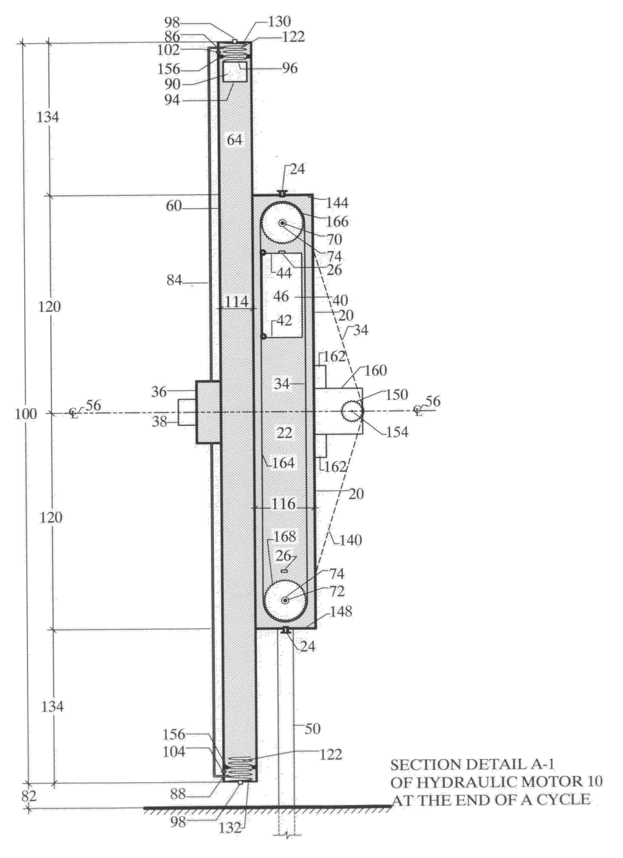
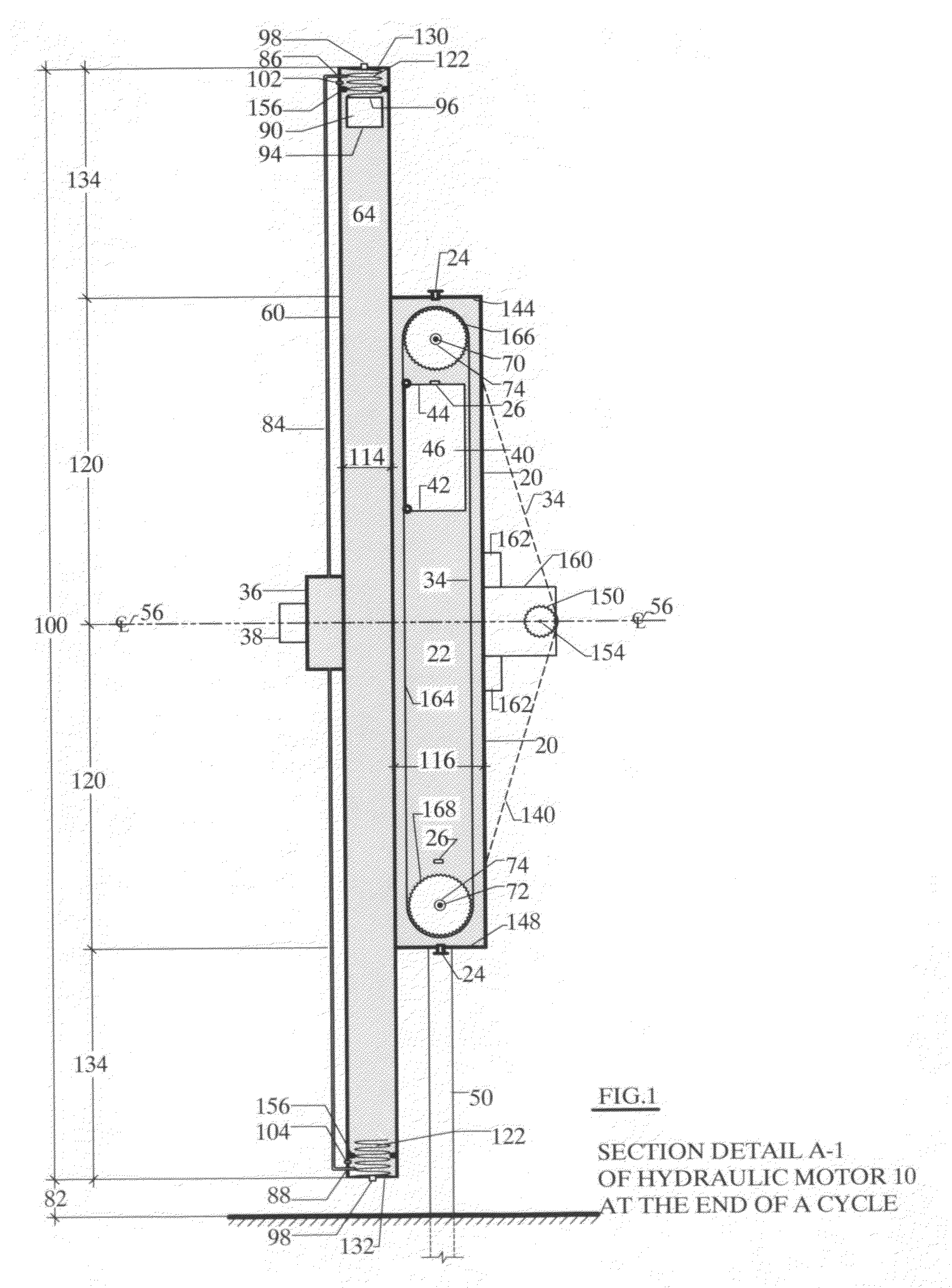
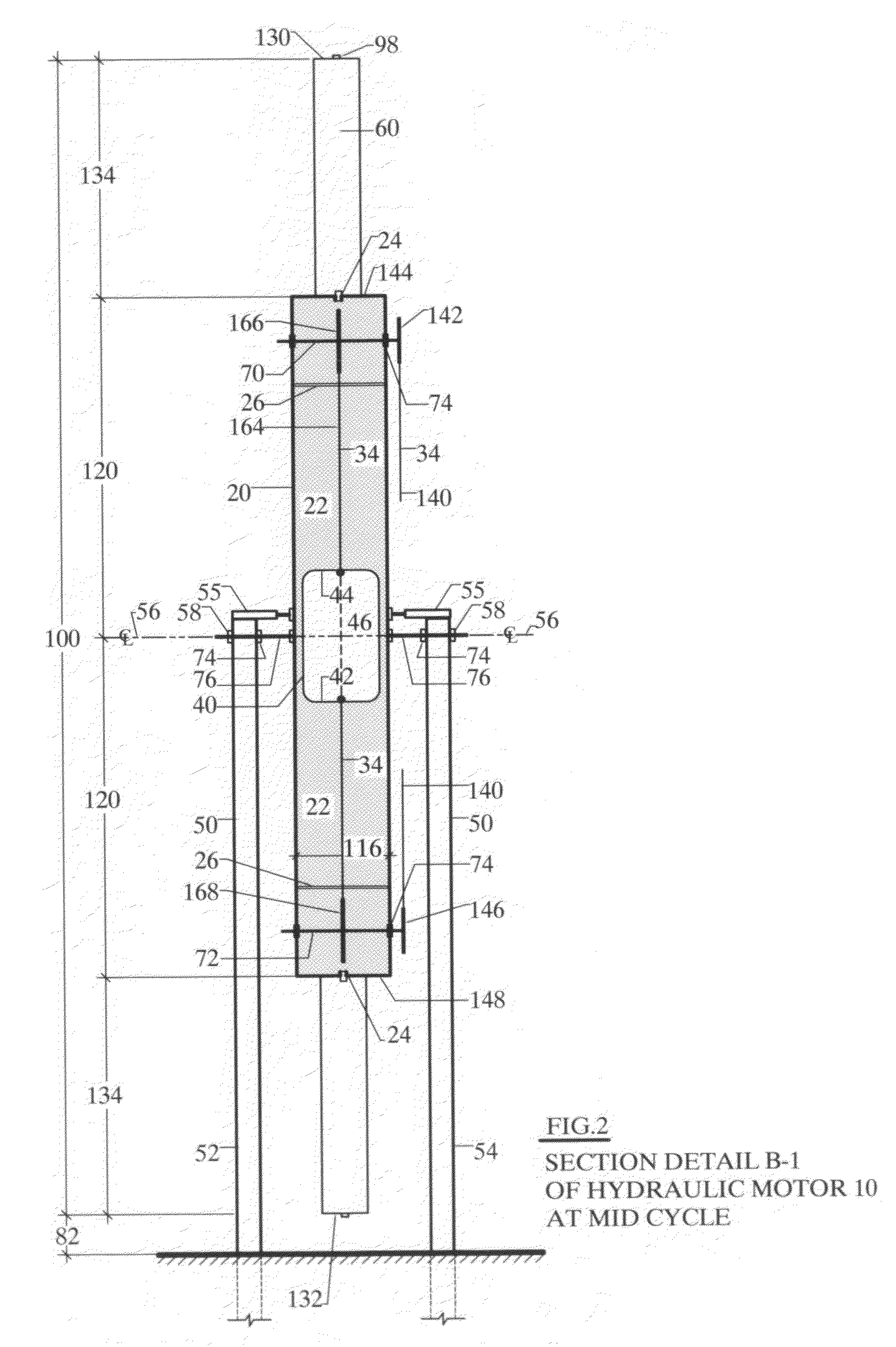
[0015]The present invention will now be described more fully hereinafter, in which the description of the preferred embodiments of the invention are discussed. Unless otherwise defined, technical and scientific terms used herein have the same meaning as commonly understood by one of ordinary skill in the art to which this invention pertains. Although methods and materials similar or equivalent to those described herein can be used in the practice of testing of the present invention, suitable methods and materials are described below. In addition, the materials, methods and examples given are illustrative in nature only and not intended to be limiting. Accordingly, this invention may be embodied in many different forms and should not be construed as limited to the illustrated embodiments set forth herein. Rather, these illustrated embodiments are provided solely for exemplary purposes so that this disclosure will be thorough and complete, and will fully convey the scope of the invent...


PUM


Abstract

A motor mounted on a structural support with a pivot at its center line which comprises a cylindrical vessel for holding a fluid in a closed system and in which a buoyant cylinder containing a lighter fluid is allowed to free float so that a continuous chain attached to each end of the buoyant cylinder may be used to transfer energy to a energy storage unit, a crank or a generator. A weighted piston that operates in a pressure tank which force a compressed gas against the piston through pre-sequenced automatic activated valves to force the piston to rise a re determined distance, causing the motor to become top heavy and rotate 180 degrees by gravity and relocks in place to repeat the cycle.

Description

CROSS REFERENCE TO RELATED APPLICATIONSReferences CitedReferenced ByU.S. Patent Documents[0001]3,194,008July 1965Baumgartner60 / 4953,961,479June 1976Anderson60 / 4965,996,344December 1999Frenette, et.Al60 / 4964,718,232January 1988Willmouth60 / 4964,683,720August 1987Deshon60 / 495STATEMENT REGARDING FEDERALLY SPONSORED RESEARCH OR DEVELOPMENT[0002]“Not Applicable”REFERENCE TO SEQUENCE LISTING, A TABLE, OR A COMPUTER PROGRAM LISTING COMPACT DISC APPENDIX[0003]“NotApplicable”BACKGROUND OF THE INVENTION[0004]The present invention relates to the field of hydraulic motors and, more particularly, to a hydrodynamic mechanical motor that uses a combination of buoyancy and gravity to create kinetic energy that can be converted into electrical energy.[0005]Motors using fluids as their principal source of energy have typically been thought of as either novelties or as large hydro turbine units associated with flowing bodies of water such as rivers or dams. In the past, buoyancy motors were typically c...

Claims


Application Information

Patent Timeline
IPC IPC(8): F03B17/02
CPCF03B17/00Y02E10/28Y02E10/20
Inventor DAVIS, STEPHEN E.
Owner DAVIS STEPHEN E
Why Eureka
Try Eureka