Combination structure of piston ring and cylinder liner for internal combustion engine

a technology of internal combustion engine and cylinder liner, which is applied in the direction of machines/engines, solid-state diffusion coating, mechanical apparatus, etc., can solve the problems of irregular protrusions and depressions that protrude from aluminum matrix, the sliding surface of the piston ring on the cylinder liner surface is not stable, and the friction damage is effectively reduced. , to achieve the effect of reducing friction damage, reducing wear and improving service li

Inactive Publication Date: 2010-12-23
NIPPON PISTONRING CO LTD
View PDF10 Cites 33 Cited by
  • Summary
  • Abstract
  • Description
  • Claims
  • Application Information

AI Technical Summary

Benefits of technology

[0030]The combination structure of the piston ring and the cylinder liner for an internal combustion engine according to the present invention minimizes wear in both the cylinder liner and the sliding surface of the piston ring, and effectively reduces damage by friction caused in a sliding operation by setting the surface roughness properties in the cylinder liner th

Problems solved by technology

Chemical treatment disclosed in Patent Document 1 is difficult in process control, and it makes hard to obtain cylinder liner surface having an even surface state stably.
So, irregular protrusions and depressions protruded from an aluminum matrix are inevitably formed on the cylinder liner surface.
As a result, touching of the sliding surface of the piston ring onto the cylinder liner surface is not stable, and a quality of an engine to be manufactured may be fluctuated.
As it can be recognized from the above description, even when the cylinder (cylinder liner) disclosed in Patent Document 1 and the piston ring disclosed in Patent D

Method used


Image

  • Combination structure of piston ring and cylinder liner for internal combustion engine
  • Combination structure of piston ring and cylinder liner for internal combustion engine
  • Combination structure of piston ring and cylinder liner for internal combustion engine

Examples


example 1

[0091]In Example 1, “the worn amount in the cylinder liner equivalent material”, “the worn amount in the first ring equivalent material” and “total worn amount that is sum of worn amount in both the cylinder liner equivalent material and the first ring equivalent material” were investigated on the seven kinds of the cylinder liner equivalent materials (“CL specimen 1” to “CL specimen 7”) in combination with “FR Specimen 3” in the first ring equivalent material respectively. Example 1 is common in using “FR Specimen 3” as the first ring equivalent material specimen. As is shown in Table 3, “FR Specimen 3” comprises the surface roughness RzJIS94 of 0.7 μm and Rpk of 0.06 μm and the values are low in the range of the surface roughness properties 2. As is shown in Table 4, the worn amounts when “FR Specimen 3” was combined with each cylinder liner equivalent material (“CL specimen 1” to “CL specimen 7”) of Example 1 were “The worn amount in the cylinder liner equivalent material” of 0.4...

example 2

[0092]In Example 2, “the worn amount in the cylinder liner equivalent material”, “the worn amount in the first ring equivalent material” and “total worn amount that is sum of worn amount in both the cylinder liner equivalent material and the first ring equivalent material” were investigated on the seven kinds in the cylinder liner equivalent materials (“CL specimen 1” to “CL specimen 7”) in combination with “FR Specimen 4” in the first ring equivalent material respectively. Example 2 is common in using the specimen “FR Specimen 4” as the first ring equivalent material. As is shown in Table 3, “FR Specimen 4” comprises the surface roughness RzJIS94 of 1.6 μm and Rpk of 0.3 μm and the values exist close to upper limit in the range of the surface roughness properties 2. As is shown in Table 4, the worn amounts when “FR Specimen 4” was combined with each cylinder liner equivalent material (“CL specimen 1” to “CL specimen 7”) of Example 2 were “The worn amount in the cylinder liner equiv...

example 3

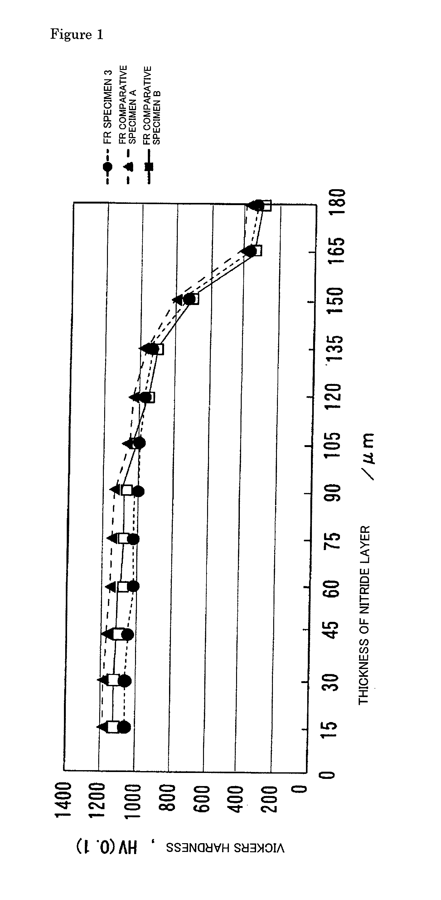
[0093]In Example 3, “the worn amount in the cylinder liner equivalent material”, “the worn amount in the first ring equivalent material” and “total worn amount that is sum of worn amount in both the cylinder liner equivalent material and the first ring equivalent material” were investigated on three kinds in the cylinder liner equivalent materials (“CL specimen 2”, “CL specimen 5” and “CL specimen 7”) in combination with “FR Specimen 1” and “FR Specimen 2” in the first ring equivalent material respectively. In Example 3, the first ring equivalent materials uses were “FR Specimen 1” and “FR Specimen 2”. As shown in Table 3, the nitride layer thickness was 40 μm, and the hardness was 980 HV0.1 in both “FR Specimen 1” and “FR Specimen 2”. When these values are compared to the nitride layer thickness in the range 30 μm to 150 μm and the hardness in the range of 900 HV0.1 to 1200 HV0.1 in the present invention, the thickness and hardness of the nitride layer in “FR Specimen 1” and “FR Sp...


PUM

PropertyMeasurementUnit
Temperatureaaaaaaaaaa
Lengthaaaaaaaaaa
Lengthaaaaaaaaaa

Abstract

An object of the present invention is to provide a cylinder structure reduced in mutual damage caused by a sliding operation of a piston ring and a cylinder liner when the piston ring having a linear expansion property which follows linear expansion of the cylinder liner made of an aluminum alloy is used. In order to achieve the object, a combination structure of the piston ring and the cylinder liner for an internal combustion engine described below is employed. In the cylinder liner for an internal combustion engine, the inner circumferential surface satisfies the conditions, a ten-point height of roughness profile (RzJIS94) of 0.5 μm to 1.0 μm, a core roughness depth (Rk) of 0.2 μm to 0.4 μm, a reduced peak height (Rpk) of 0.05 μm to 0.1 μm and a reduced valley depths (Rvk) of 0.08 μm to 0.2 μm. In the piston ring, the sliding surface against to an inner circumferential surface in the cylinder liner satisfies the conditions, a ten-point height of roughness profile (RzJIS94) of not more than 1.6 μm and a reduced peak height (Rpk) of not more than 0.3 μm. The piston ring is used at a contact pressure of 0.03 MPa to 0.2 MPa against to the inner circumferential surface of the cylinder liner.

Description

TECHNICAL FIELD[0001]The present invention relates to a combination structure of a piston ring and a cylinder liner for an internal combustion engine. The present invention particularly relates to an optimal combination of a cylinder liner that constitutes an inner circumferential surface of a cylinder made of an aluminum alloy that holds a piston and a piston ring provided on a piston which slides along the cylinder liner.BACKGROUND ART[0002]In recent years, a body weight of automobiles has been reduced to improve efficiency of fuel consumption. So, it is required to reduce a weight of each component while maintaining or improving its performance, quality, and a price for each component of the automobile. For example, for a cylinder that holds a piston of an internal combustion engine, ferrous materials such as cast iron, steel, and the like have been used in view of a mechanical property and a price required for a cylinder. However, although the cylinder made of such a ferrous mat...

Claims


Application Information

Patent Timeline
IPC IPC(8): F02F1/00
CPCC22C21/00C22C21/02C22C38/02C22C38/58F16J10/04C23C30/00F02F1/20F02F3/00F16J9/26C23C8/26
Inventor OGAWA, KATSUAKIHIRASE, TSUGANE
Owner NIPPON PISTONRING CO LTD
Why Eureka
Try Eureka