Flexural vibration piece, flexural vibrator, and electronic apparatus

Inactive Publication Date: 2010-12-23
SEIKO EPSON CORP
View PDF10 Cites 9 Cited by
  • Summary
  • Abstract
  • Description
  • Claims
  • Application Information

AI Technical Summary

Benefits of technology

[0024]According to the flexural vibration device and electronic apparatus, they include a flexural vibration piece in which the vibrating arm is made thinner, and a semicondu

Problems solved by technology

A vibrating arm which has a groove, or the like, is such that its rigidity decreases, it is not possible to obtain a stable flexural vibration by utilizing the characteristics of the base material of the vibrating arm, and a downsizing is difficult.
However, with the heretofore technology, wires connecting electrodes provided on each vibrating arm, sandwiching the piezoelectric layer, are of a complex configuration adjacent to each other or intersecting across an insulating film.
This kind of complex wiring is such that t

Method used


Image

  • Flexural vibration piece, flexural vibrator, and electronic apparatus
  • Flexural vibration piece, flexural vibrator, and electronic apparatus
  • Flexural vibration piece, flexural vibrator, and electronic apparatus

Examples


embodiment

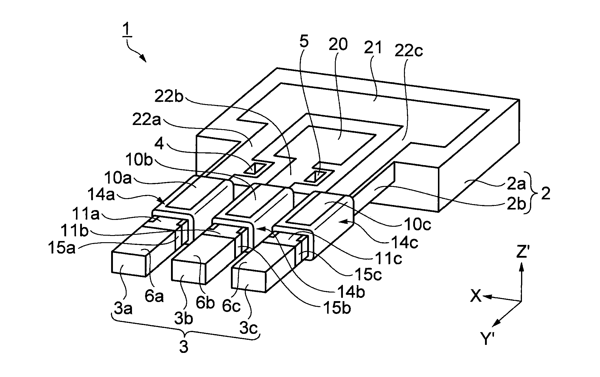
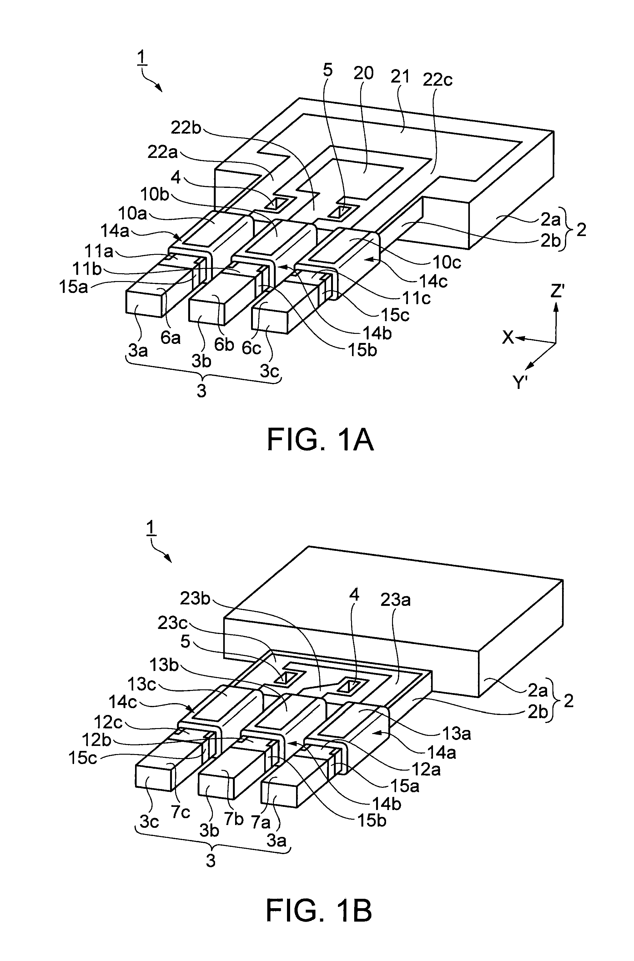
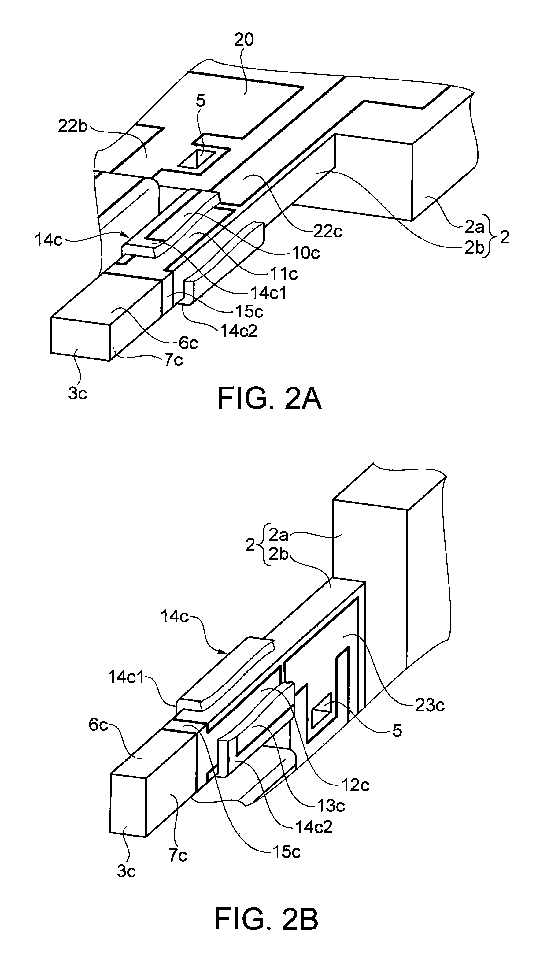
[0034]FIG. 1A is a perspective view showing an external appearance of the crystal vibration piece according to the embodiment seen from the front side, and FIG. 1B is a perspective view showing an external appearance of the crystal vibration piece seen from the rear side. Also, FIG. 2A being a perspective view showing the configuration of the piezoelectric layer seen from the front side, and FIG. 2B a perspective view showing the configuration of the piezoelectric layer seen from the rear side, they show details of the piezoelectric layer by displaying a partial cross-section. The crystal vibration piece (flexural vibration piece) 1 is such that the side on which a main portion 2a and a thin portion 2b of a base portion 2 are in the same plane is the front side, as shown in FIG. 1A, the side on which the main portion 2a and thin portion 2b of the base portion 2 form a level difference is the rear side, as shown in FIG. 1B, and the front-rear direction is the thickness.

[0035]The crys...

modification example 1

[0068]The crystal vibration piece 1 includes the three vibrating arms 3a, 3b, and 3c, and performs a so-called out-of-plane vibration but, not being limited to this, the vibration piece may be of a configuration including a number of vibrating arms 3 other than three, and furthermore, may be of a configuration such that it performs an in-plane vibration wherein the vibrating arms are disposed in the vibration direction, rather than an out-of-plane vibration.

modification example 2

[0069]The lower electrodes 11 and 12 of the crystal vibration piece 1 are a metal film with a two-layer structure of titanium (Ti) and platinum (Pt) in order to promote the orientation of the aluminum nitride (AlN) but, not being limited to this, they may also be a metal film with a single layer structure of titanium (Ti), or the like, provided that it promotes the orientation of the aluminum nitride (AlN).


PUM


Abstract

A flexural vibration piece includes: a base portion; a vibrating arm extending from the base portion and having a first surface, a second surface opposing the first surface, and side surfaces connecting the first surface and second surface, wherein a laminated structure including a first electrode, a second electrode, and a piezoelectric layer disposed between the first electrode and second electrode, is formed on each of the first surface and second surface, the piezoelectric layer formed on the first surface side and the piezoelectric layer formed on the second surface side have mutually opposite polarization directions, and the first electrode formed on the first surface side and the first electrode formed on the second surface side are connected to each other.

Description

BACKGROUND[0001]1. Technical Field[0002]The present invention relates to a flexural vibration piece, a flexural vibrator, and an electronic apparatus, which have configurations suitable for downsizing.[0003]2. Related Art[0004]To date, a flexural vibration piece has been disclosed which includes a pair of piezoelectric elements spaced apart on the front surface of a vibrating arm, as disclosed in, for example, JP-A-2008-11348. The flexural vibration piece is such that, by a drive voltage being applied to each of the piezoelectric elements, and each of the piezoelectric elements being deformed, the vibrating arm is caused to flex in a predetermined direction. In this case, the piezoelectric elements, being of a configuration wherein a piezoelectric layer is sandwiched by two electrodes, are such that the drive voltage is applied to the two electrodes, deforming the piezoelectric layer. Also, a configuration has also been disclosed wherein a further pair of piezoelectric elements are ...

Claims


Application Information

Patent Timeline
IPC IPC(8): H01L41/047H01L41/04H01L41/09H01L41/18H01L41/187H01L41/22H01L41/29H03H3/02H03H9/19H03H9/215
CPCH03H9/21H03H9/176
Inventor TAKIZAWA, TERUO
Owner SEIKO EPSON CORP
Why Eureka
Try Eureka