[0010]In the first switching
power supply unit according to an embodiment of the present invention, a DC input voltage inputted from input terminal pair is switched in an
inverter circuit to generate an AC voltage. Then, the AC voltage is transformed by transformer and then rectified by rectification
smoothing circuit. Thus a DC output voltage is outputted from output terminal pair. Here, in the rectification
smoothing circuit, the first
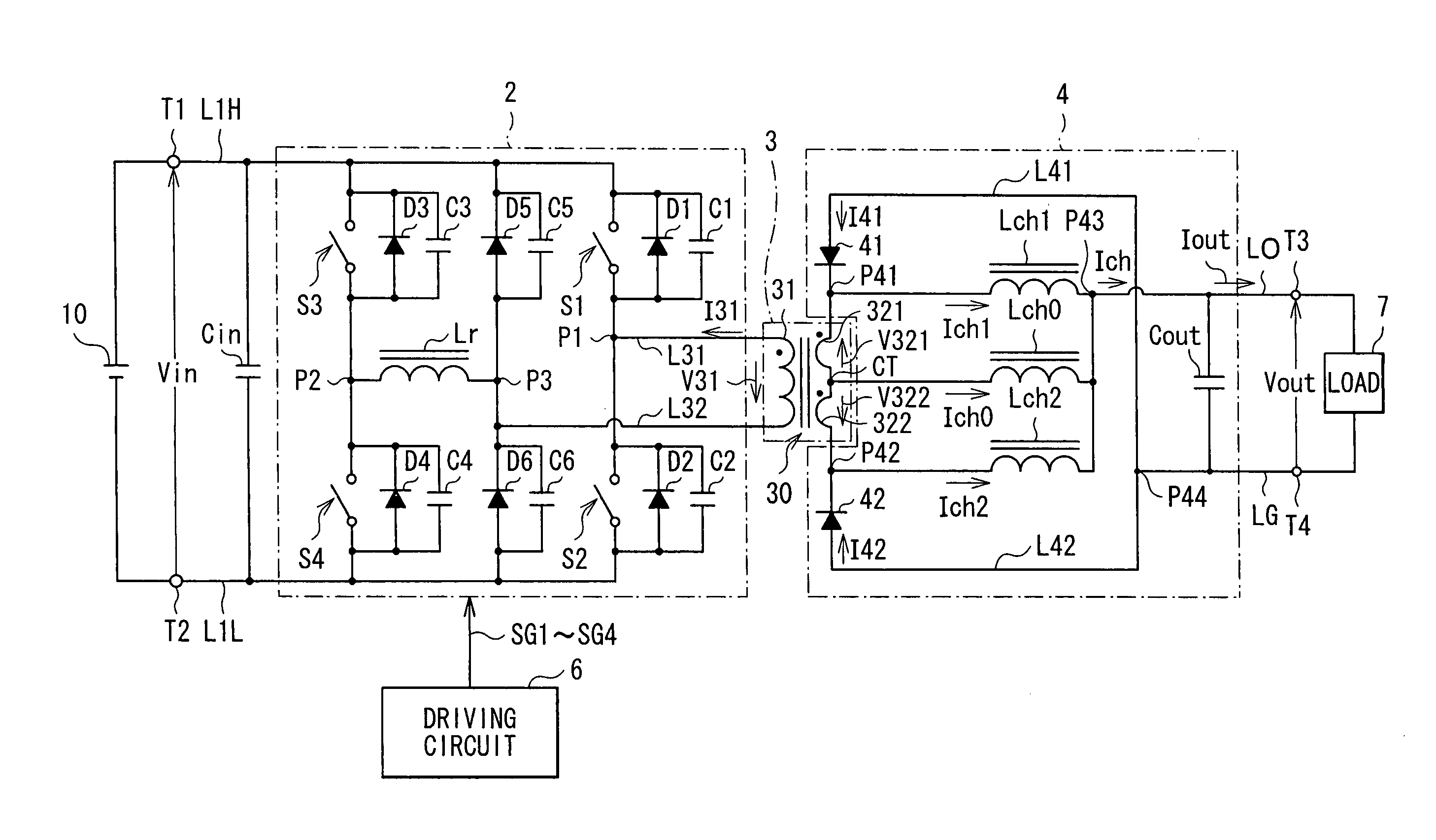
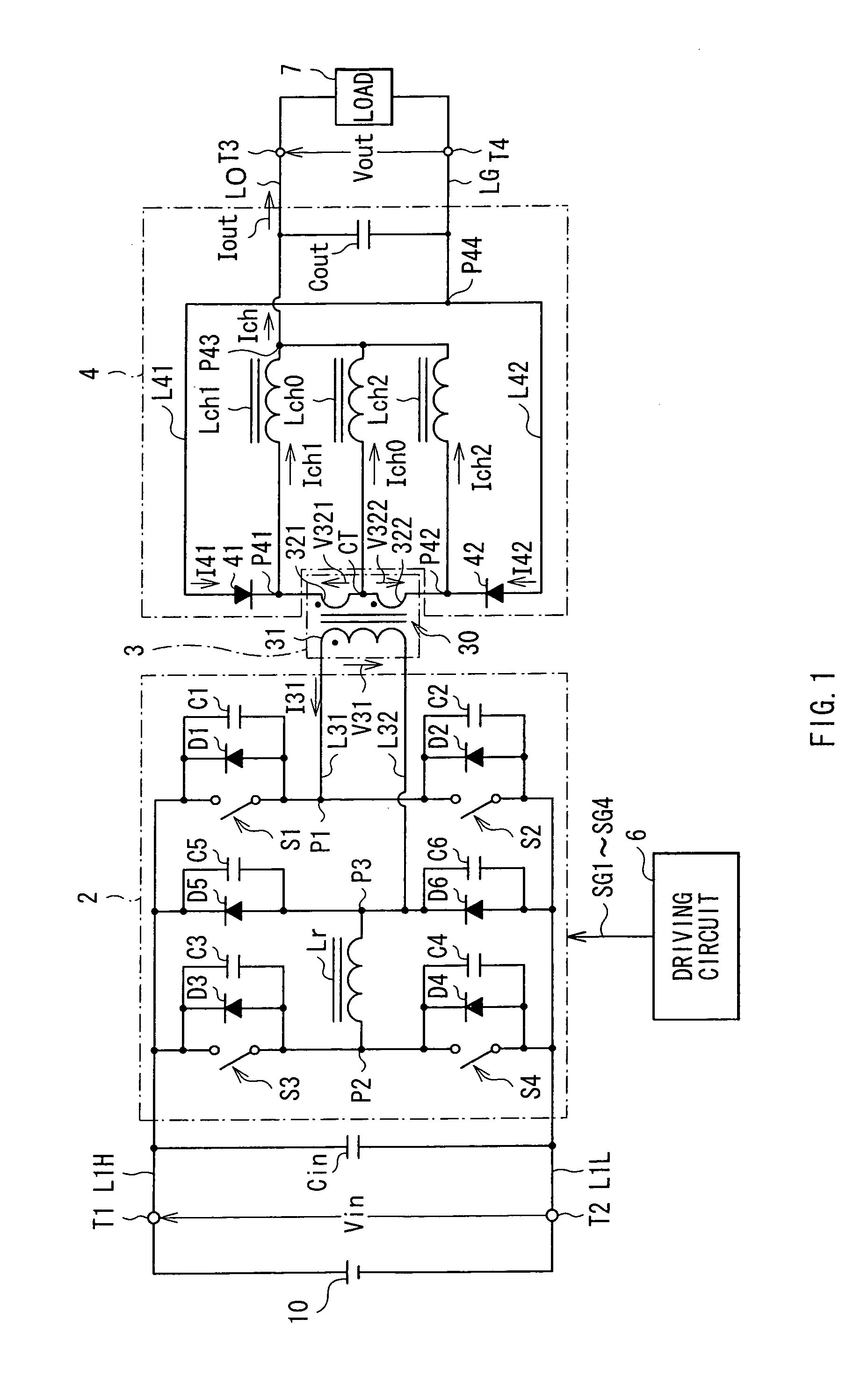
rectifier device is arranged between a connection point of one ends of the first secondary winding and the second choke coil and one end of the capacitive element. The second
rectifier device is arranged between a connection point of one ends of the second secondary winding and the third choke coil and one end of the capacitive elements. A connection point of the other ends of the first and second secondary windings is connected to one end of the first choke coil, and a connection point of the other ends of the first to third choke coils is connected to the other end of the capacitive element. In this configuration, output currents are always split into the three choke coils (the first to third choke coils) in the rectification smoothing circuit. As a result, an amount of current dealt-with in each choke coil is reduced.
[0011]According to the first switching
power supply unit of an embodiment of the present invention, when
inductance of the first to third choke coils are defined as L1, L2 and L3 respectively, it is preferred that they satisfy the expression L1<L2=L3. In this configuration, output currents may be easily split into the three choke coils.
[0017]In the first and second embodiments, the primary winding may be wound around so that closed magnetic paths are formed inside the
magnetic core from the four legs to the two base-plates due to currents which flow through the primary winding, and among four legs, a first couple of magnetic fluxes respectively generated inside the first couple of legs are both directed in a first direction, and a second couple of magnetic fluxes respectively generated inside the second couple of legs are both directed in a second direction which is opposite to the first direction. Alternatively, the primary winding may be wound around so that closed magnetic paths are formed inside the
magnetic core from the four legs to the two base-plates due to currents which flow through the primary winding, the four closed magnetic paths each passing through both adjacent two of the four legs and the two base-plates and then returning. In this configuration, reduction of flux density in
magnetic core is achieved due to the dispersion of flux path compared with the case where a U-shaped core is employed, thereby reducing the core loss. Further since heat
radiation path is expanded compared with the case of an E-shaped core, cooling of the primary and secondary windings gets more easy as with the cooling of the magnetic core itself. As a result, cost reduction is achieved while increasing reliability of product.
[0020]In the second switching
power supply unit according to an embodiment of the present invention, the primary winding may be wound around so that closed magnetic paths are formed inside the magnetic core from the four legs to the two base-plates due to currents which flow through the primary winding, and among four legs, a first couple of magnetic fluxes respectively generated inside the first couple of legs are both directed in a first direction, and a second couple of magnetic fluxes respectively generated inside the second couple of legs are both directed in a second direction which is opposite to the first direction. Alternatively, the primary winding may be wound around so that closed magnetic paths are formed inside the magnetic core from the four legs to the two base-plates due to currents which flow through the primary winding, the four closed magnetic paths each passing through both adjacent two of the four legs and the two base-plates and then returning. In this configuration, reduction of flux density in magnetic core is achieved due to the dispersion of flux path compared with the case where a U-shaped core is employed, thereby reducing the core loss. Further since heat
radiation path is expanded compared with the case of an E-shaped core, cooling of the primary and secondary windings gets more easy as with the cooling of the magnetic core itself. As a result, cost reduction is achieved while increasing reliability of product.
[0021]In the switching power supply unit according to an embodiment of the present invention, in a rectification smoothing circuit, the first rectifier device is arranged between a connection point of one ends of the first secondary winding and the second choke coil and one end of the capacitive element, the second rectifier device is arranged between a connection point of one ends of the second secondary winding and the third choke coil and one end of the capacitive element, and a connection point of the other ends of the first and second secondary windings is connected to one end of the first choke coil, and a connection point of the other ends of the first to third choke coils is connected to the other end of the capacitive element. In this manner, the amount of current dealt-with in each choke coil is reduced and DC superposing characteristic of the choke coils may be reduced (inductance becomes less likely to be saturated). Therefore, the
operating point of the output power smoothing choke coil may be more lowered than ever. Thereby, a smaller choke coil with high inductance is available, while the
power loss in the choke coil may be reduced.

