
Stage structure and heat treatment apparatus

a heat treatment apparatus and stage technology, applied in lighting and heating apparatus, furnaces, muffle furnaces, etc., can solve the problems of large heat escape from the central portion of the stage, cracking or even breaking of the stage, etc., to enhance the in-plane uniformity of heat treatment of processing objects and prevent the breakage of the stage

Inactive Publication Date: 2010-12-23
TOKYO ELECTRON LTD
View PDF8 Cites 16 Cited by
  • Summary
  • Abstract
  • Description
  • Claims
  • Application Information

AI Technical Summary

Benefits of technology

[0028]The stage structure and the heat treatment apparatus according to the present invention can achieve the following advantageous effects:

Problems solved by technology

However, because the stage 2 and the support post 4 have been bonded by thermal diffusion, there is an unavoidable escape of a large amount of heat from the central portion of the stage 2 into the support post 4.
Consequently, concentration of a large thermal stress will occur in the central portion of the stage 2, which can cause cracking or even breakage of the stage 2.

Method used


Image

  • Stage structure and heat treatment apparatus
  • Stage structure and heat treatment apparatus
  • Stage structure and heat treatment apparatus

Examples


Embodiment Construction

[0041]Preferred embodiments of the stage structure and the heat treatment apparatus of the present invention will now be described in detail with reference to the drawings.

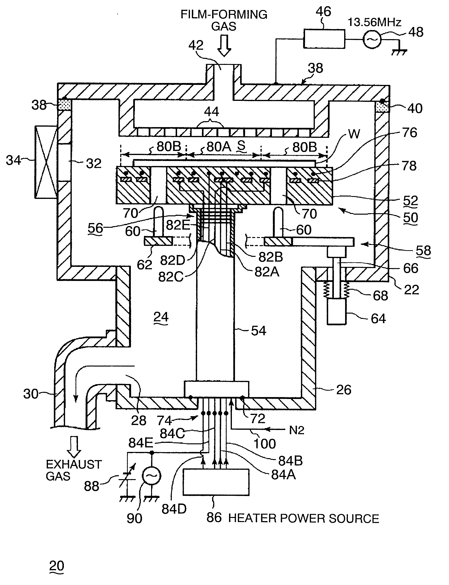
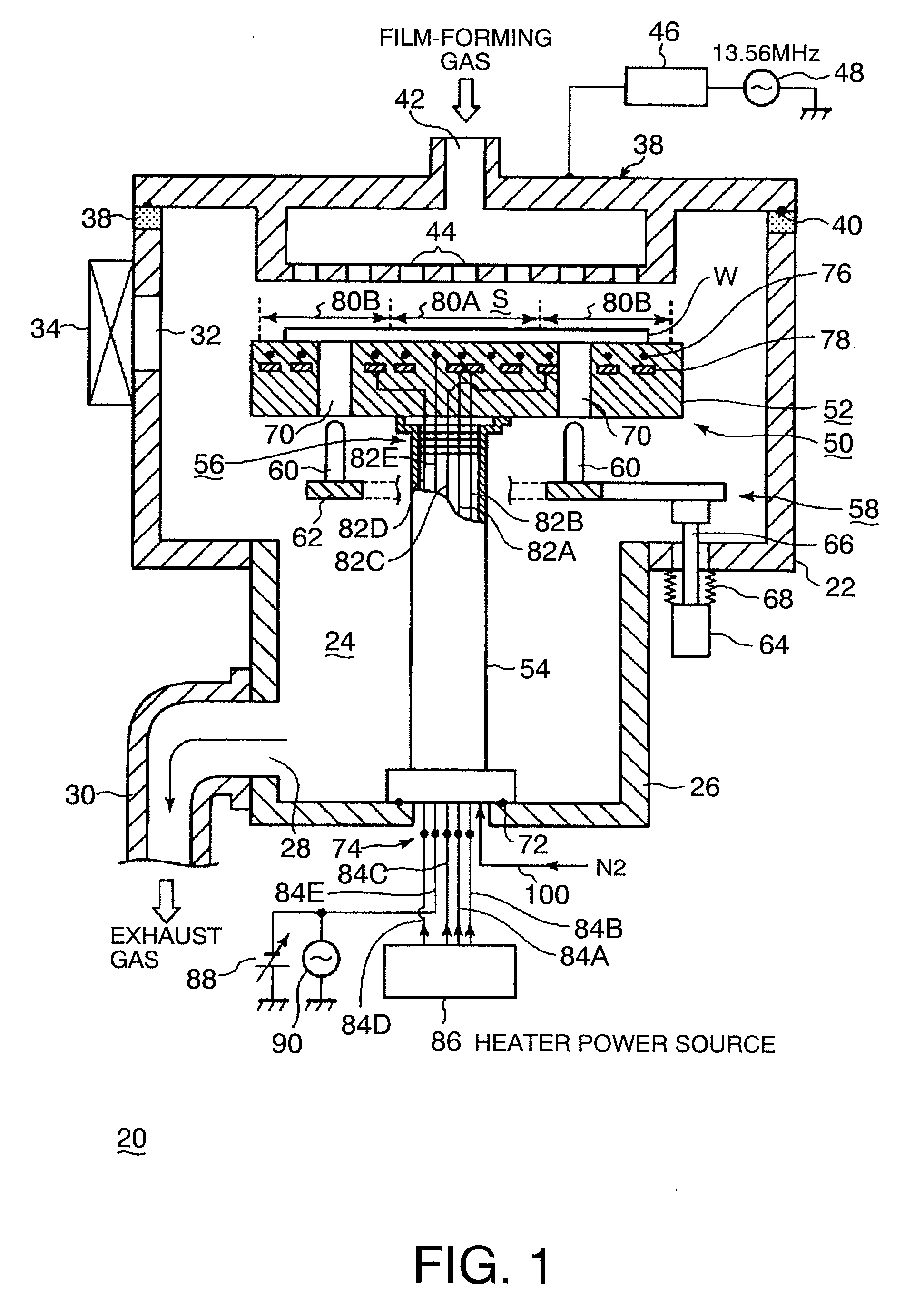
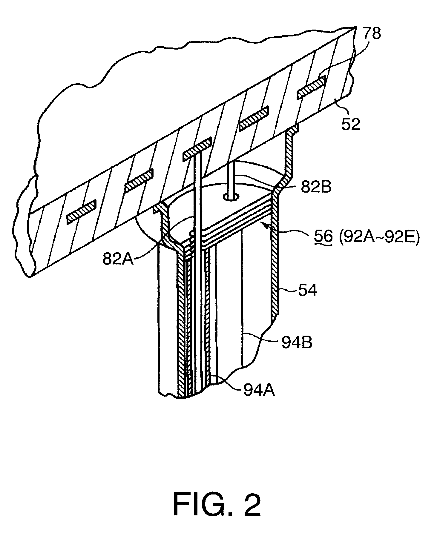
[0042]FIG. 1 is a diagram showing the construction of a heat treatment apparatus using a stage structure according to the present invention; FIG. 2 is a partially enlarged perspective view schematically showing a portion of the stage structure; FIG. 3 is a cross-sectional view schematically showing the stage structure; FIG. 4 is an enlarged cross-sectional view schematically showing the joint between a stage and a support post; and FIG. 5 is an exploded perspective view showing exemplary support rods that support heat reflecting plates.

[0043]A parallel flat-plate type of plasma heat treatment apparatus is herein illustrated as an exemplary heat treatment apparatus. As shown in FIG. 1, the heat treatment apparatus 20 includes a treatment container 22 made of e.g. an aluminum alloy and formed in a cylindrical shape....


PUM

PropertyMeasurementUnit
Shapeaaaaaaaaaa
Heataaaaaaaaaa
aaaaaaaaaa

Abstract

There is provided a stage structure which can prevent the formation of a cool spot in the central portion of a stage, thereby preventing breakage of the stage, and can enhance the in-plane uniformity of heat treatment of a processing object.The stage structure, provided in a treatment container of a heat treatment apparatus, for placing thereon a semiconductor wafer W as a processing object to be heat treated, includes: a stage 52 for placing the processing object on it; and a cylindrical support post 54 jointed to the center of the lower surface of the stage and supporting the stage. A heat reflecting section 56 is provided at an upper position within the support post and close to the lower surface of the stage. The use of the heat reflecting section 56 prevents the formation of a cool spot in the central portion of the stage 54.

Description

TECHNICAL FIELD[0001]The present invention relates to a heat treatment apparatus and a stage structure for carrying out a predetermined heat treatment of a processing object, such as a semiconductor wafer.BACKGROUND ART[0002]In the manufacturing of a semiconductor integrated circuit, a processing object such as a semiconductor wafer is generally subjected to repetition of various treatments, such as film formation, etching, heat treatment, reforming, crystallization, etc. to form a desired integrated circuit. When carrying out such various treatments, a treatment gas necessary for an intended treatment, for example, a film-forming gas and a halogen gas for film formation, ozone gas, etc. for reforming, or an inert gas such as N2 gas, O2 gas, etc. for crystallization, is introduced into a treatment container.[0003]In the case of a one-by-one type heat treatment apparatus which carries out heat treatment of semiconductor wafers in a one-by-one manner, a stage, e.g. having a built-in r...

Claims


Application Information

Patent Timeline
IPC IPC(8): F27B5/16B23Q3/00
CPCC23C16/4586H01L21/68792H01L21/67115H01L21/67103
Inventor TORIYA, DAISUKEYAMAMOTO, HIROHIKO
Owner TOKYO ELECTRON LTD
Learn More