Ultrasound transducer

a technology of ultrasound transducer and ultrasound image, which is applied in the field of real-time medical ultrasound imaging system, can solve the problems of inability to obtain useful information, and achieve the effects of excellent response time, precise movement, and very rapid movement and stopping

Inactive Publication Date: 2010-12-23
SIGNOSTICS LTD
View PDF19 Cites 52 Cited by
  • Summary
  • Abstract
  • Description
  • Claims
  • Application Information

AI Technical Summary

Benefits of technology

[0016]Ultrasonic motors are very precise in movement and can be positioned to nanometer accuracy

Problems solved by technology

Useful information cannot be obtained if the transducer is itse

Method used


Image

  • Ultrasound transducer
  • Ultrasound transducer
  • Ultrasound transducer

Examples


Embodiment Construction

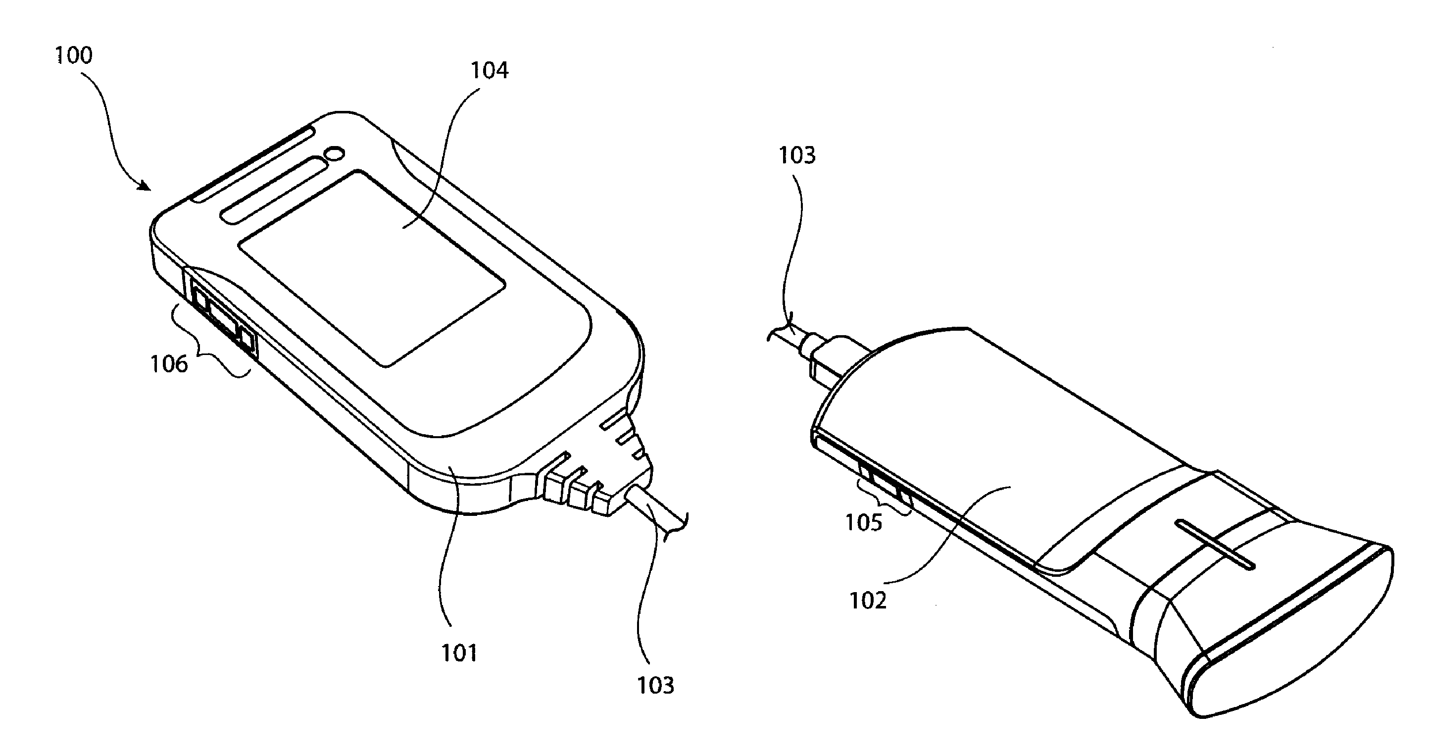
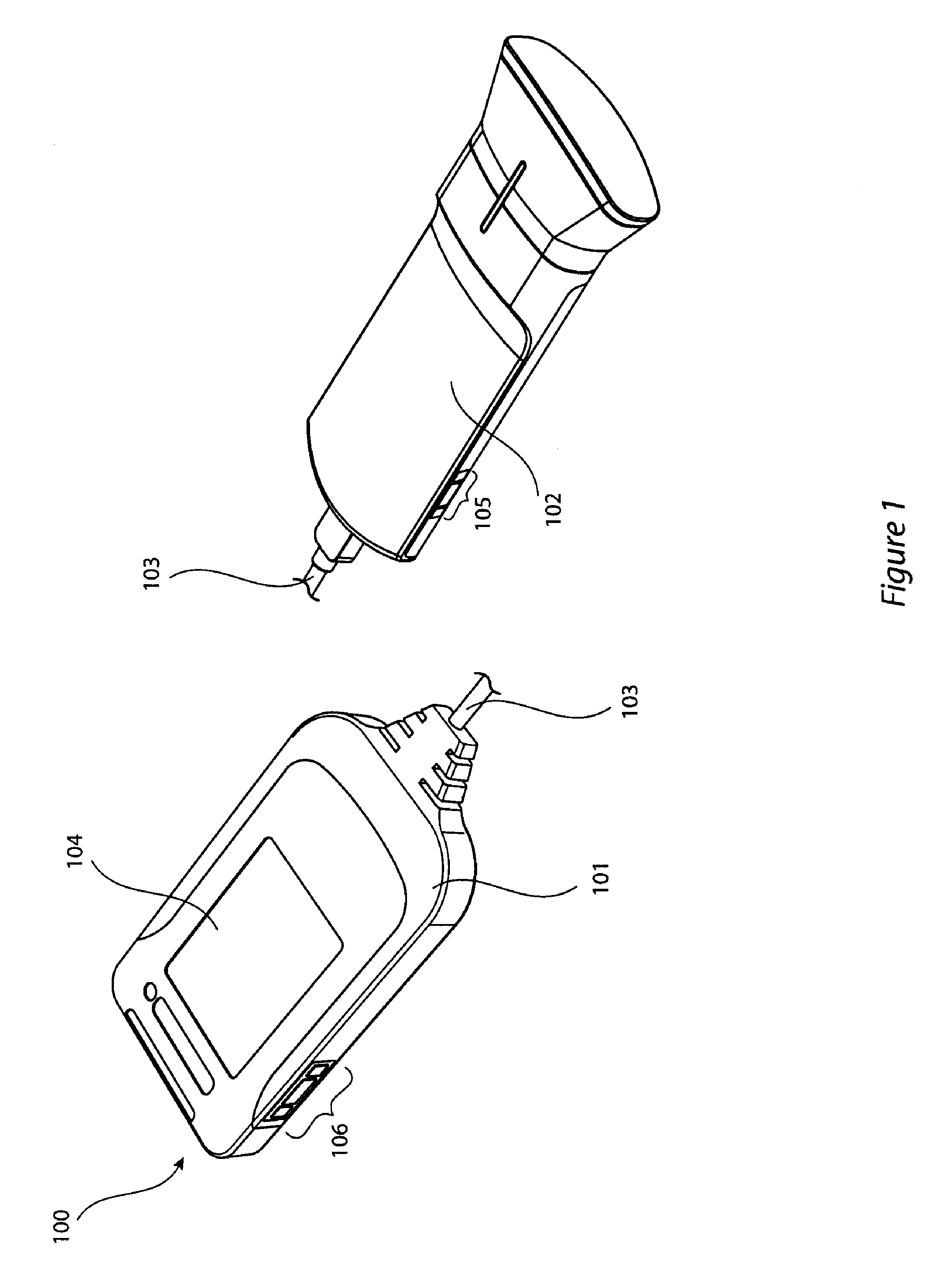
[0043]Now referring to the illustrations, and in particular to FIG. 1, there is shown a view of an exemplary ultrasound scan apparatus 100. This includes a display unit 101, and a probe unit 102. These are connected by communications cable 103. The display unit has a display 104. The display screen may be a touch screen allowing a user to control the functionality of the display unit and the probe unit. In the illustrated version, control members 106 are provided on the display unit, in the form of push buttons and a scrollwheel. Control members 105 are provided on the probe unit. Either or both of these control members may be absent.

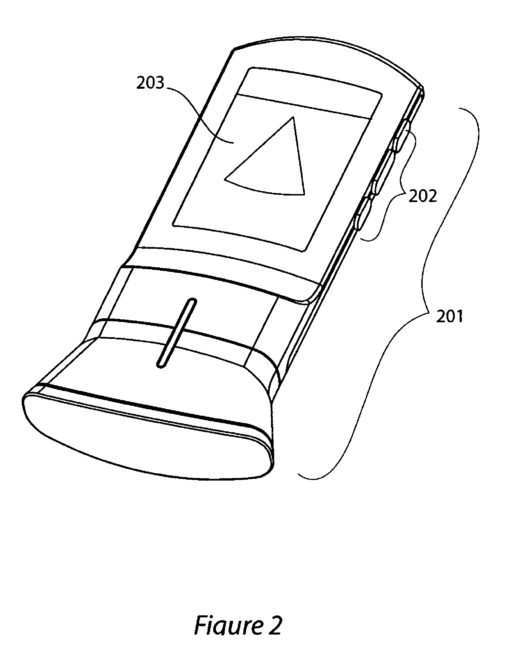
[0044]FIG. 2 shows an alternative version where the features of the display unit are incorporated in the probe unit 201. There is a display 203 included in the probe unit. This may be a touchscreen and provide a user interface to control the function of the ultrasound scan apparatus. There may be provided control members 202 on the probe unit for access...


PUM


Abstract

An ultrasound system having a transducer probe unit including at least one transducer for transmitting and receiving ultrasonic signals, wherein the transducer is moved with respect to the probe unit in a repetitive motion by an ultrasonic motor.

Description

CROSS-REFERENCE TO RELATED APPLICATIONS [0001]This application claims priority under 35 USC §119(a) to Australian Provisional Application 2009902886 filed Jun. 23, 2009, the entirety of which is incorporated by reference herein.TECHNICAL FIELD [0002]The present invention relates to a real time medical ultrasound imaging system. In particular it relates to such a system employing a motor driven array.BACKGROUND ART[0003]Ultrasound is a non invasive technique for generating image scans of interior body organs. There are a number of types of real time ultrasound systems supporting a wide variety of ultrasound transducers. These systems can be divided into electronic systems such as phased array, curvilinear array, and linear array transducers which employ fully electronic techniques for beam forming and for directing the ultrasonic beam; and mechanical systems where a transducer or a transducer array is moved mechanically to direct the beam.[0004]Mechanical scanners are traditionally t...

Claims


Application Information

Patent Timeline
IPC IPC(8): A61B8/14A61B8/00
CPCG01S7/003G01S7/52047G01S7/5208G01S7/52096G01S15/8934A61B8/56G01S15/895G01S15/8959G01S15/8979G10K11/352G01S15/8945A61B8/4245A61B8/4444A61B8/4461A61B8/4483A61B8/4488
Inventor EL-AKLOUK, ESSABARTLETT, STEWARTPARKER, JOHN
Owner SIGNOSTICS LTD
Why Eureka
Try Eureka