
Complex ocean power system combining sluice power and ocean current power

a technology of complex ocean power system and ocean current, which is applied in water-power plants, machines/engines, electric generator control, etc., can solve the problems of large initial investment, sporadic generation, and rare examples of large-scale ocean current power generation in the world, so as to maximize the operating rate of power facilities, increase the value of use and uniformity, and increase the effect of electric power

Inactive Publication Date: 2010-12-30
JANG KYUNG SOO +3
View PDF6 Cites 17 Cited by
  • Summary
  • Abstract
  • Description
  • Claims
  • Application Information

AI Technical Summary

Benefits of technology

[0028]A complex ocean power system combining sluice power generation and ocean current power generation according to the present invention may maximize an operating rate of power facilities by using the incoming seawater into the lake and the fast flow of the seawater discharged into the sea through sluice conduits of sluice structures and installing bi-directional ocean current generators for generating electricity in ocean current, which flows in the opposite direction each other during flood tide and ebb tide. At this time, the ocean current that passes through the sluice conduits of the sluice structures according to the present invention is capable of producing high electric power by ocean current generators because the seawater, which passes the sluice structures and the sluice conduits, has kinetic energy having higher value in use and uniformity than natural seawater.
[0029]Further, the ocean current generators for ocean current power generation, which are far more simple than the huge and complex turbine generators for tidal power generation to be used in the turbine structures of a tidal power plant for the existing tidal power system, are installed in the sluice conduits of the tidal power dam of the tidal power system, for sluice power generation, thereby performing bidirectional power generation during flood tide and ebb tide. Thus, it is not needed to construct the turbine structures of the existing tidal power plants, and thus, construction costs can be largely reduced.
[0030]First of all, the present invention brings about the possibility of the development and production of ocean current generators for ocean current power generation based on only domestic technologies, in replacement of the development of the turbine generator for tidal power generation, which has been regarded as a technology barrier, inspires a motivation for mass production of necessary ocean current generators along with the exploitation of new domestic markets, and provides with opportunities capable of occupying in advance technologies and markets in the fields of the world's ocean current power generation and sluice power generation, which are in the step of verification to be truly commercialized.

Problems solved by technology

On the other hand, its disadvantages include sporadic generation and large initial investment due to the construction of power transmission lines if the power plant is far from land.
However, while several tidal power plants have been practically applied, one example of large-scale ocean current power generation is rare in the world.
The reason for this is that it was not easy to find a proper site on which to install turbine generators due to the lack of natural sea areas where the seawater flow is fast enough for ocean current power generation.
Furthermore, even if the average speed of ocean current were satisfactory, it is difficult to achieve a structural stability of the turbine generators and reliable control of generation volume if the speed distribution is uneven according to the seabed topography of the area where an ocean current power plant is to be installed.

Method used


Image

  • Complex ocean power system combining sluice power and ocean current power
  • Complex ocean power system combining sluice power and ocean current power
  • Complex ocean power system combining sluice power and ocean current power

Examples


Embodiment Construction

[0034]Hereinafter, embodiments of the present invention will now be described in greater detail with reference to the accompanying drawings.

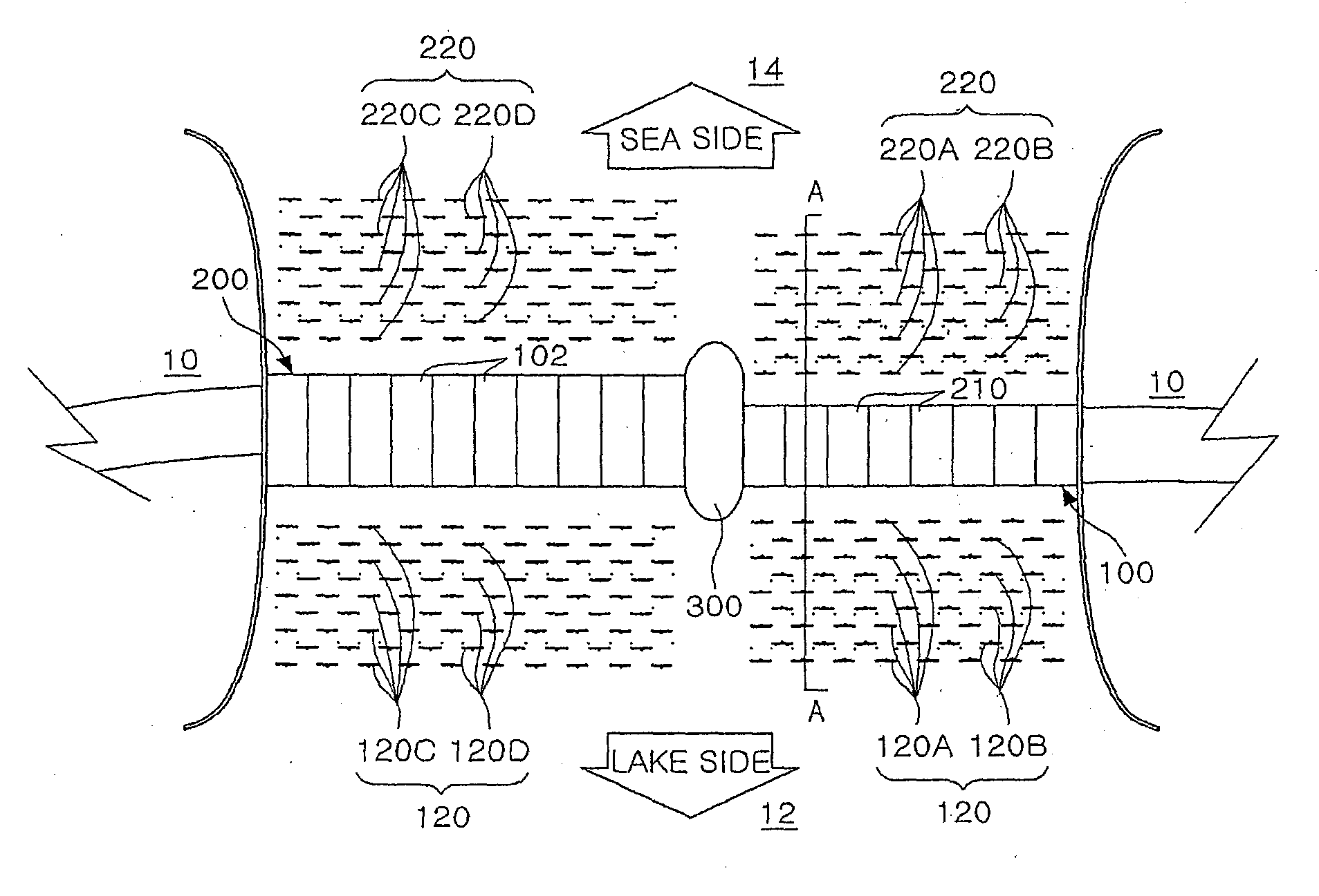
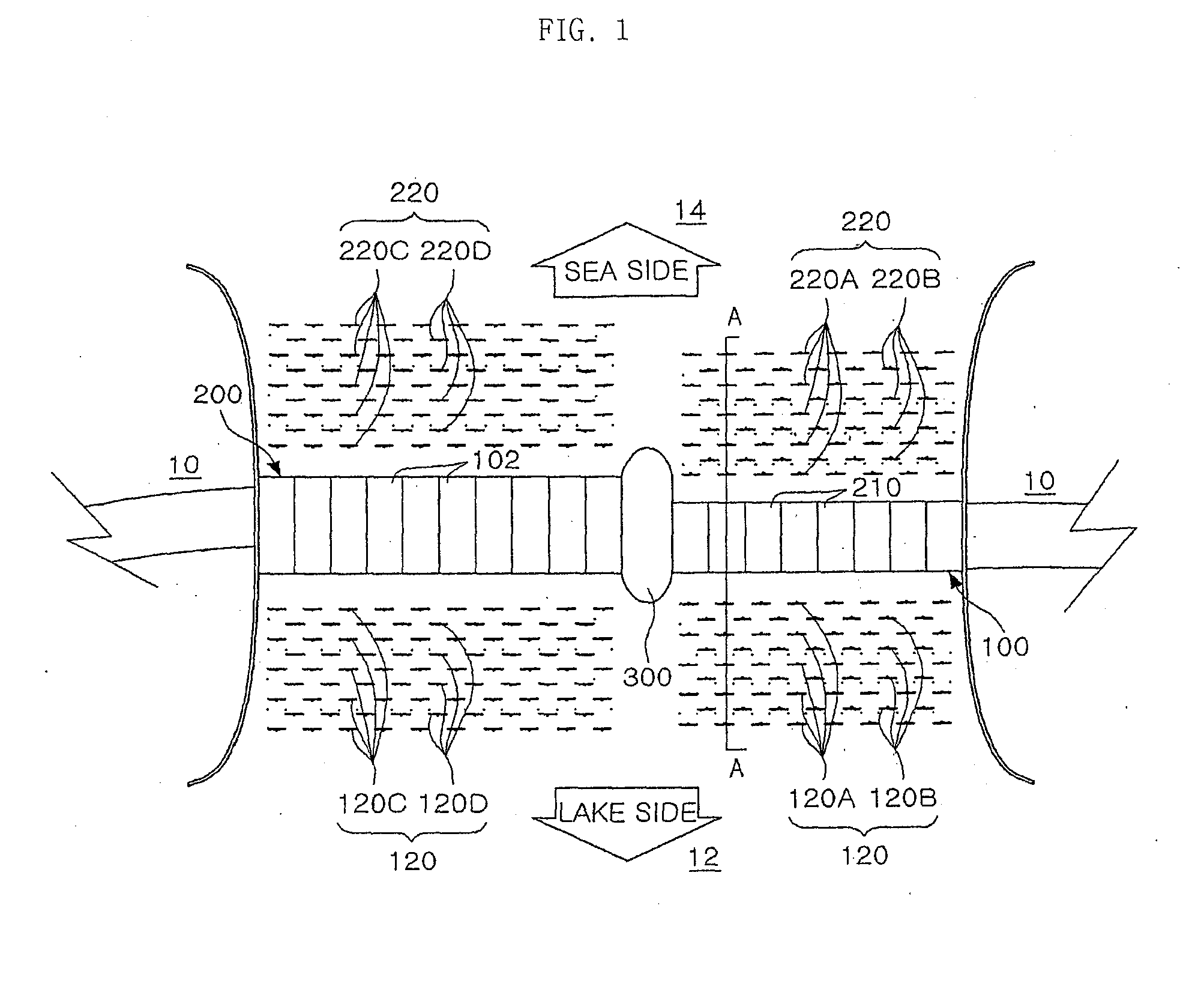
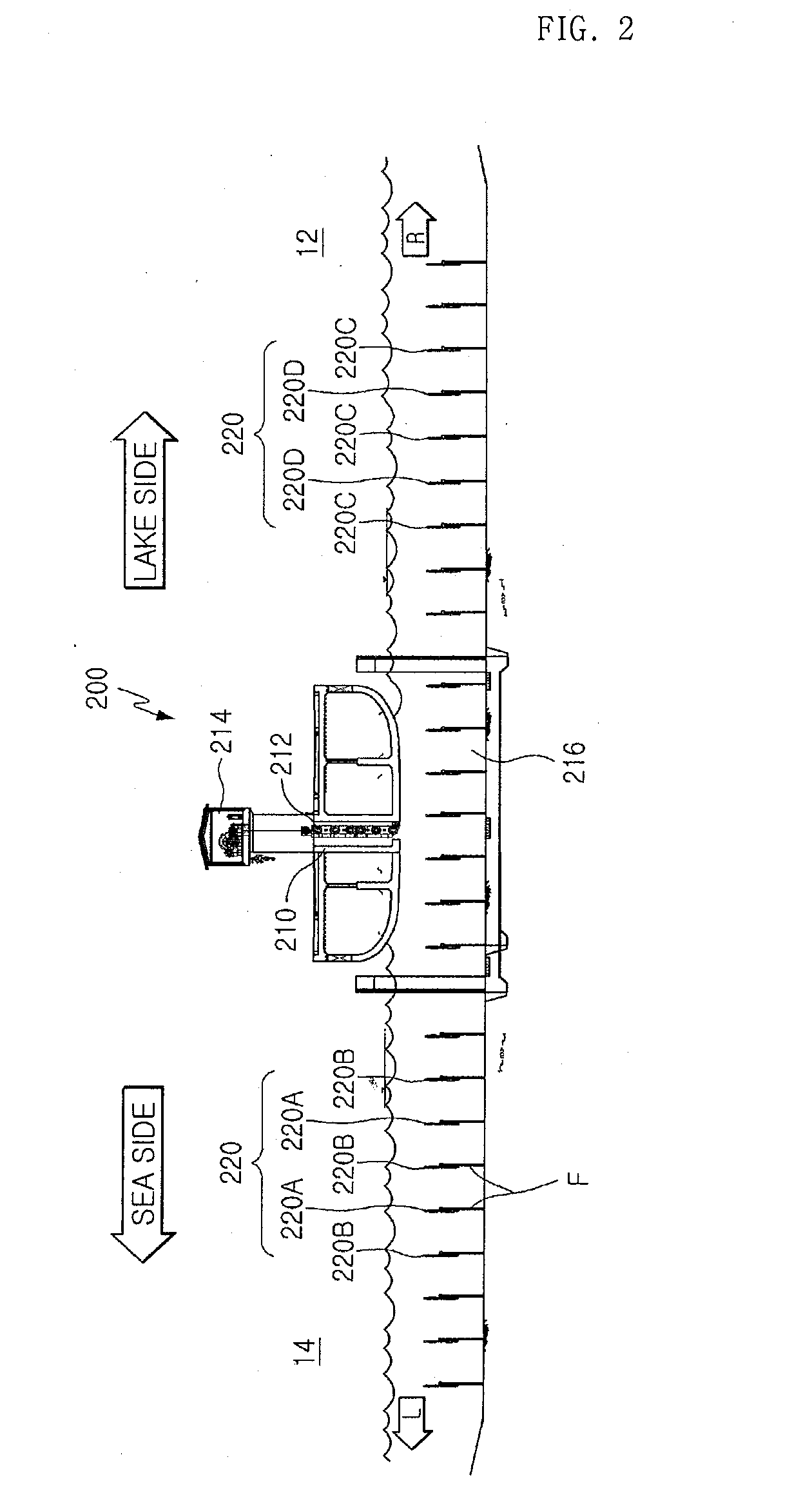
[0035]FIG. 1 is a plane view illustrating a complex ocean power system combining sluice power generation and ocean current power generation according to an embodiment of the present invention that two kinds of sluice structures of a tidal power dam in which a length of sluice conduits is different are connected with a middle connection structures; and FIG. 2 is a side view illustrating sluice conduits in sluice structures of a tidal power dam and ocean current generators in a sea side and a lake side according to an embodiment of the present invention taken along a line A-A in FIG. 1.

[0036]As illustrated in FIG. 1, the complex ocean power system combining sluice power generation and ocean current power generation according to the present invention needs to construct barrages 10 in the place where a large difference between tides and ebbs occurs....


PUM


Abstract

There is provided with a complex ocean power system combining ocean current power generation for generating electricity by forming a plurality of ocean current generators in front and rear of sluice structures of tidal power dams and sluice power generation for generating electricity by forming a plurality of ocean current generators in sluice conduits of the sluice structures, comprising: constructing barrages, which cross over the sea, to make up a lake; installing sluice structures of tidal power dams between the barrages 10 to generate electricity by changing a potential energy difference between seawaters caused by tides and ebbs to kinetic energy; installing ocean current generators in front and rear of the sluice structures and in the sluice conduits of the sluice structures to generate electricity by rotating turbine blades using the flow of the incoming seawater from a sea side into a lake side during flood tide and the flow of the seawater discharged from the lake side into the sea side during ebb tide; and installing sluice gates in the sluice structures 102, 210 to close and open the sluice conduits during flood tide and ebb tide.

Description

TECHNICAL FIELD[0001]The present invention relates to a complex ocean power system combining sluice power generation and ocean current power generation, and more particularly, to a complex ocean power system combining sluice power generation and ocean current power generation which is capable of increasing an operating rate of ocean current generators and efficiently generating electrical power energy by using the incoming seawater into a lake through sluice conduits of sluice structures connected with barrages, which cross over the lake and the sea, or a fast flow of seawater discharged to the sea. In particular, the present invention adopts a system for generating power using ocean current, which flows with a fast speed through the sluice structures to change a potential energy difference between seawaters, which is generated in front and rear of the barrage by tides and ebbs, to kinetic energy.BACKGROUND ART[0002]The present invention relates to tidal power generation and ocean c...

Claims


Application Information

Patent Timeline
IPC IPC(8): F03B13/08F03B13/26
CPCE02B9/08E02C1/00Y02E10/28F03B13/268F03B13/264Y02E10/30Y02A10/30Y02A20/00F03B13/08F03B13/26Y02E10/20
Inventor JANG, KYUNG SOOLEE, JUNG EUNJANG, JAE WONJANG, SEUNG WON
Owner JANG KYUNG SOO
Learn More