
Piezoelectric resonator

a resonator and piezoelectric technology, applied in piezoelectric/electrostrictive/magnetostrictive devices, piezoelectric/electrostriction/magnetostriction machines, electrical equipment, etc., can solve problems such as deterioration of piezoelectric resonators, insufficient plane parallelism of piezoelectric plates, and poor performance of piezoelectric plates for high frequency applications. achieve excellent characteristics and reduce the effect of spur

Active Publication Date: 2010-12-30
DAISHINKU CORP
View PDF4 Cites 14 Cited by
  • Summary
  • Abstract
  • Description
  • Claims
  • Application Information

AI Technical Summary

Benefits of technology

[0063]As described above, according to the present invention, piezoelectric resonator can be obtained in which spurious vibrations are suppressed and which have excellent characteristics.

Problems solved by technology

For example, in some cases the planes of their piezoelectric plate are insufficient in plane parallelism due to working conditions or variations in working.
In those cases, spurious vibrations are driven intensely, and therefore the characteristics of piezoelectric resonator may be deteriorated.
The above problem is attributed to spurious vibrations coming to the surface as higher frequencies are used, and piezoelectric plates for high frequency applications in which their driving region is formed thinly are particularly susceptible to such a problem.
And further, in voltage-controlled piezoelectric oscillators in which the frequency of their main vibration is varied by changing external voltage, the above problem is brought to the fore when their frequency is varied considerably.
There is a high possibility that the variations in the frequency of their main vibration couple with the spurious vibration described above, which has sometimes caused the problems of the jump phenomenon of their frequency occurring and the driving of their vibration becoming unstable.

Method used


Image

  • Piezoelectric resonator
  • Piezoelectric resonator
  • Piezoelectric resonator

Examples


embodiment 1

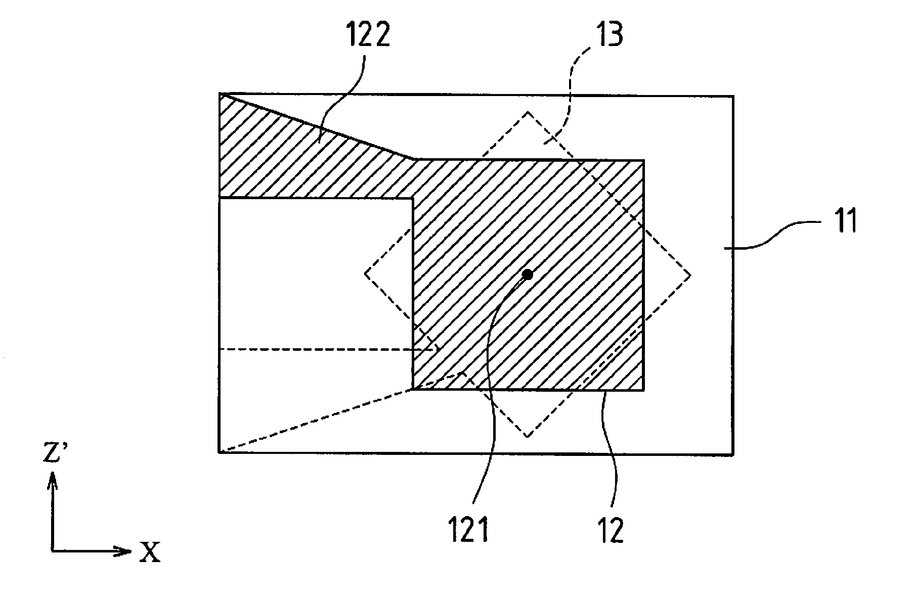
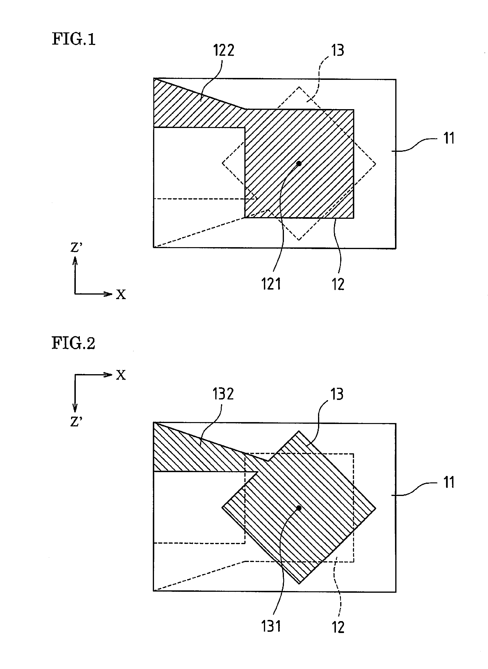
[0086]Embodiment 1 of the present invention will be described below with reference to the drawings. In this embodiment, a case will be described where structures according to the invention are applied to AT-cut crystal resonator that operate in a thickness-shear vibration mode. FIG. 1 is a plan view of a piezoelectric plate according to Embodiment 1 of the invention, and FIG. 2 is a bottom view of the piezoelectric plate of FIG. 1.

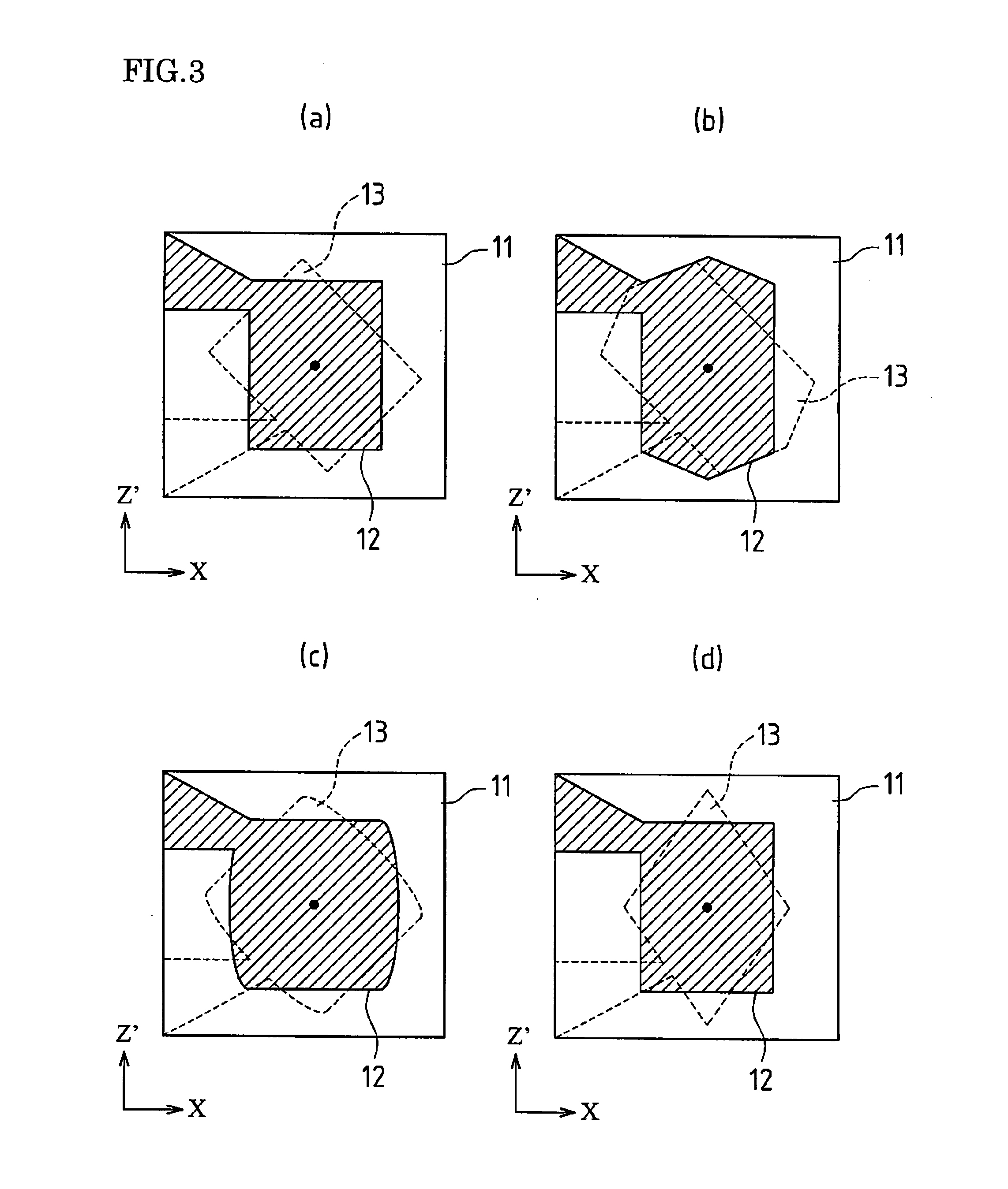
[0087]As the piezoelectric plate 11 a rectangular and flat-shaped, AT-cut crystal plate (that generates thickness-shear vibration) is used; in the central regions of the front and rear surfaces of the plate, driving electrodes 12 and 13, having a substantially square shape when viewed from above, are formed, respectively. The driving electrodes 12 and 13 are formed such that they have the same shape and area, for example and that the centers 121 and 131 of the electrodes 12 and 13 directly face each other with the piezoelectric plate 11 disposed therebetwe...

embodiment 2

[0124]In the following, Embodiment 2 of the present invention will be described with reference to the drawings. In this embodiment, a case will be described where structures according to the invention is applied to AT-cut crystal resonator that operates in a thickness-shear vibration mode. FIG. 13 is a plan view of a piezoelectric plate according to Embodiment 2 of the invention, and FIG. 14 is a bottom view of the piezoelectric plate of FIG. 13.

[0125]As the piezoelectric plate 21 a rectangular and flat-shaped, AT-cut crystal plate (that generates thickness-shear vibration) is used; in the central regions of its front and back sides, driving electrodes 22 and 23 are formed such that they have a substantially octagonal shape when viewed from above. The driving electrodes 22 and 23 have the same shape and the same area, for example, and are formed such that their centers 220 and 230 directly face each other with the piezoelectric plate 21 disposed therebetween (the front and back driv...


PUM


Abstract

A piezoelectric resonator includes a pair of driving electrodes and a pair of lead electrodes that are formed facing each other on the frontside and backside of a piezoelectric plate that operates in a thickness-shear vibration mode. The front and back driving electrodes are formed such that they each have one or more pairs of parallel sides and have the same shape, and their centers face each other. The parallel sides of one of the front and back driving electrodes are formed parallel with either the X-axis or the Z′-axis of the piezoelectric plate, but the parallel sides of the other driving electrodes are formed without being parallel with the X-axis and Z′-axis thereof.

Description

TECHNICAL FIELD [0001]The present invention relates to piezoelectric resonator and specifically to the electrode structures of piezoelectric resonator.BACKGROUND ART[0002]In piezoelectric resonator having a thickness vibration-type piezoelectric plate such as an AT-cut crystal plate, generally a pair of driving electrodes are formed directly facing each other on the front and rear surfaces of the piezoelectric plate, and alternating voltage is applied to the driving electrodes. The characteristics of such piezoelectric resonator depend on the structure of their driving electrodes. For example, by using large-sized electrodes, their vibration region can be enlarged, their series resonance resistance can be improved, and their variable frequency range can be broadened. And further, the characteristics of piezoelectric resonator significantly depend on the characteristics of their piezoelectric plate as well. For example, in some cases the planes of their piezoelectric plate are insuff...

Claims


Application Information

Patent Timeline
IPC IPC(8): H01L41/047
CPCH01L41/047H03H9/19H03H9/132H03H9/0211H10N30/875
Inventor KOYAMA, SHINICHI
Owner DAISHINKU CORP
Learn More