Radar architecture

a radar and antenna technology, applied in the field of radar systems, can solve the problems of system failure, system wearout and breakage, and the influence of amplitude and phase of radio waves, and achieve the effect of eliminating the drawbacks associated with the operation

Active Publication Date: 2010-12-30
SRC INC
View PDF3 Cites 164 Cited by
  • Summary
  • Abstract
  • Description
  • Claims
  • Application Information

AI Technical Summary

Benefits of technology

[0014]The present invention addresses the needs described above by providing a radar architecture that substantially eliminates the drawbacks associated with both conventional radar systems and MIMO systems while retaining the benefits. The present invention is directed to a radar system that is dynamically reconfigurable to search any desired volume in real-time. In doing so, the present invention optimizes the tradeoff between detectability and accuracy in accordance with real-time mission requirements.

Problems solved by technology

One of the drawbacks of this approach relates to the cost and reliability of the mechanical equipment used to rotate the antenna.
When ever a system uses moving parts, the system will ultimately wear out and break.
Moreover, the amplitudes and phases of the radio waves constructively and destructively interfere with each other to create a composite radar beam having a predetermined radiation pattern.
The other side of the coin, i.e., the drawbacks associated with the MIMO architecture, relates to the increased processing requirements.
In other words, implementing a MIMO system is challenging because of the intense processing requirements associated with MIMO architectures.
The aforementioned processing requirements translate into cost, size, weight and power consumption realities that make MIMO architectures impractical to implement.
Moreover, providing extremely high transmit power from edge-located omni-directional transmit antennas in a volume search application is impractical.
Omni-directional transmit antennas waste radar energy in portions of angle space that are not a part of the desired search volume.
In addition, very long coherent integration times are not practical for the detection of a target with high Doppler shift due to range smearing during integration, unless range resolution is decreased significantly.
This is not desirable for most volume search radars.
An excessively large matched filter bank is required to process the waveforms and achieve a reasonable response from moving targets.
Again, this requires a signal processor that has a very significant size, weight and cost, and one that consumes an inordinate amount of power.

Method used


Image

  • Radar architecture
  • Radar architecture
  • Radar architecture

Examples


Embodiment Construction

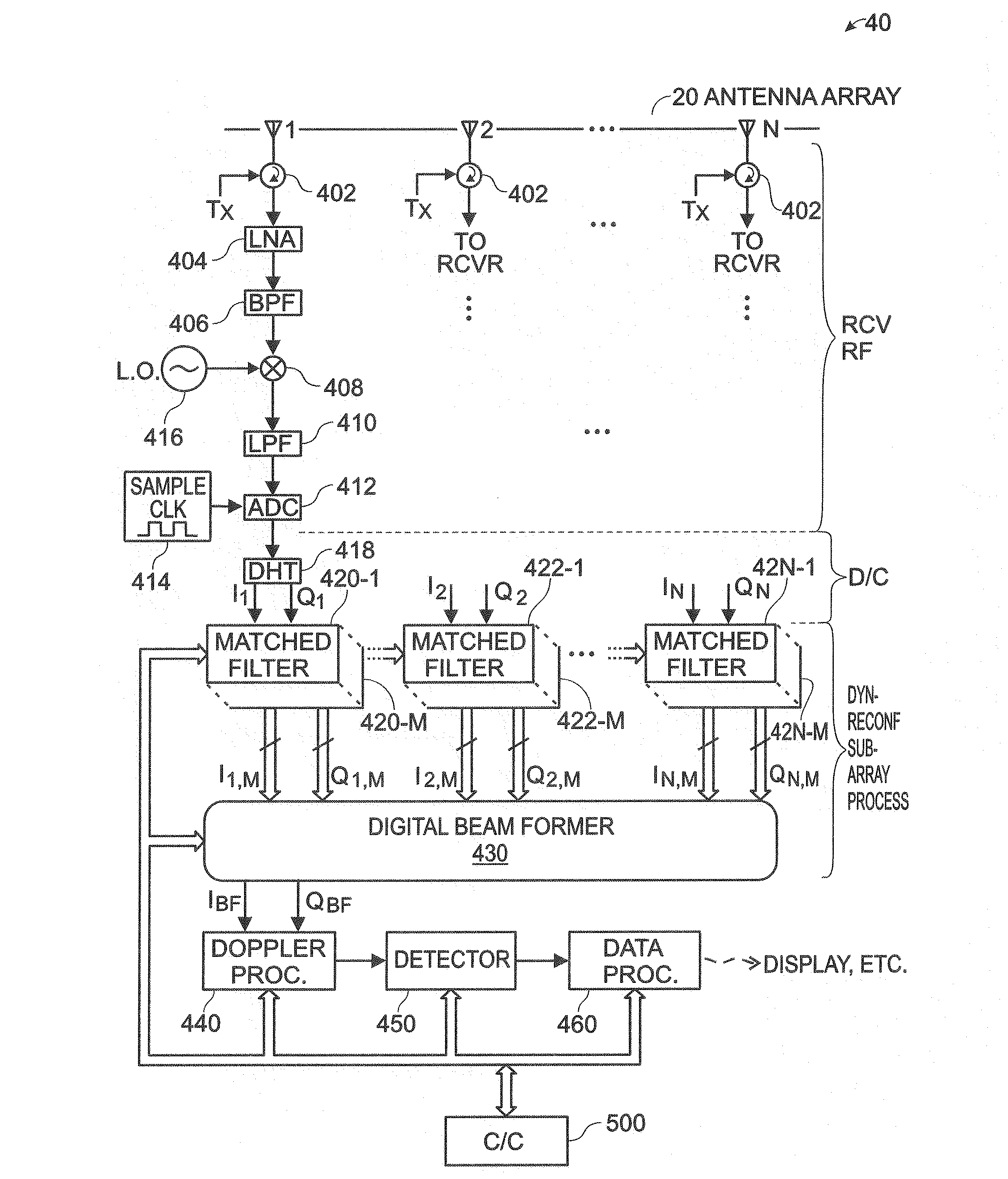
[0030]Reference will now be made in detail to the present embodiments of the invention, examples of which are illustrated in the accompanying drawings. Wherever possible, the same reference numbers will be used throughout the drawings to refer to the same or like parts. An illustrative embodiment of the radar architecture of the present invention is shown in FIG. 1, and is designated generally throughout by reference numeral 10.

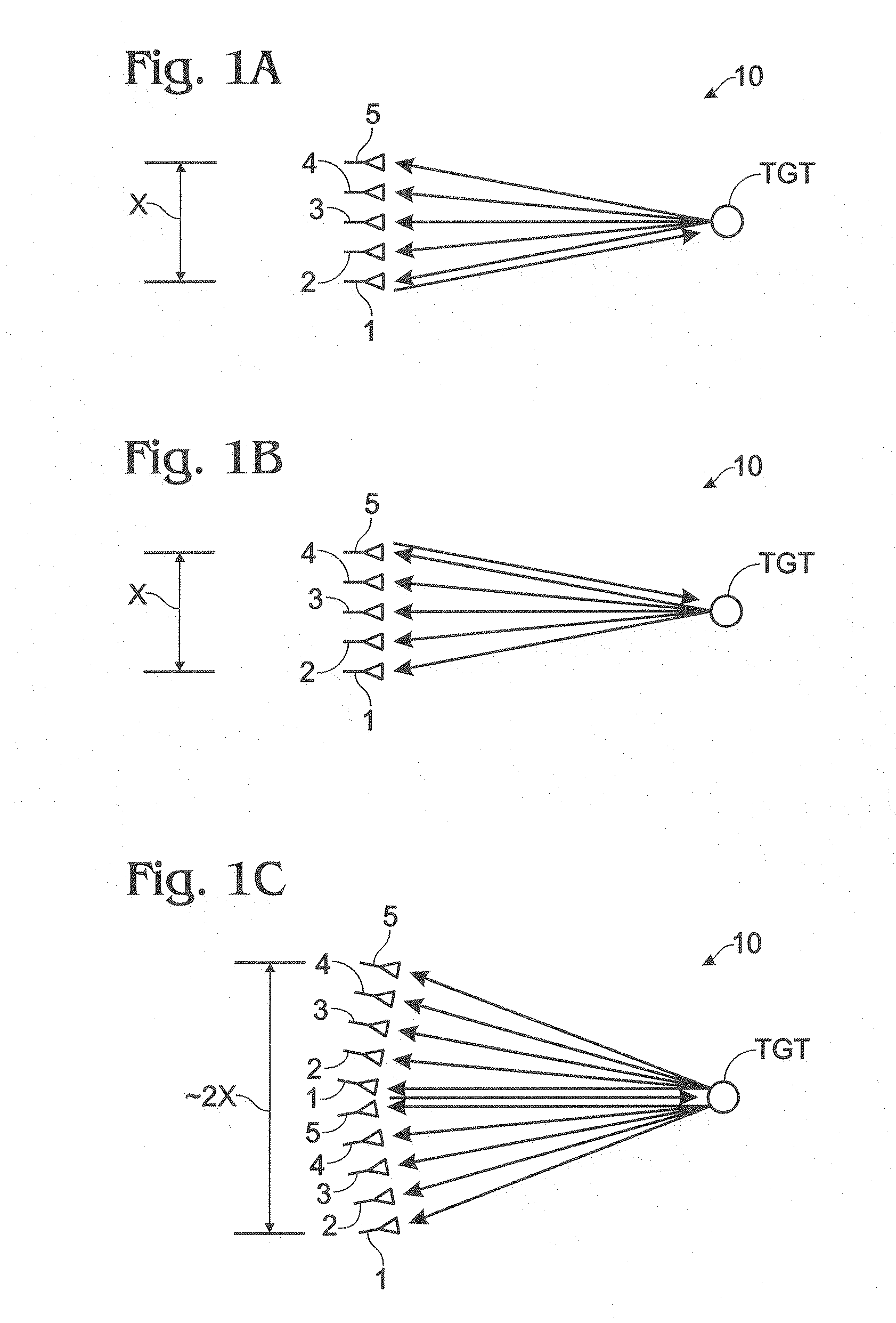
[0031]As embodied herein, and depicted in FIGS. 1A-1C, a diagrammatic depiction of a virtual array in accordance with the present invention is disclosed. FIGS. 1A-1C show a linear array of five antenna elements 1-5 and illustrates the benefit of using multiple transmit subarrays. In FIG. 1A, antenna element 1 is used as both a transmit phase center and a receive element. Antenna elements 2-5 are only used to receive. In FIG. 1B, antenna element 5 is used as both a transmit phase center and a receive element. Antenna elements 1-4 are only used to receive. If e...


PUM


Abstract

The present invention is directed to a radar system that includes an antenna array having a plurality of antenna elements and a plurality of transmit antenna phase centers. A transmitter portion is coupled to the antenna array. The transmitter portion is configured to transmit a plurality of transmit beams characterized by a transmit beam pattern. The transmit beam pattern has a predetermined transmit beamwidth that is a function of the number of orthogonal transmit waveforms. The predetermined transmit beamwidth substantially fills a predetermined angular volume. Each of the plurality of transmit beams includes a corresponding one of the plurality of orthogonal transmit waveforms. Each of the plurality of transmit beams is transmitted by a corresponding one of the plurality of transmit antenna phase centers. The number of orthogonal transmit waveforms is less than the plurality of antenna elements. A receiver portion is also coupled to the antenna array. The receiver portion is configured to extract a plurality of orthogonal receive signal components from a received signal provided by the antenna array. The plurality of orthogonal receive signal components corresponds to the plurality of orthogonal transmit waveforms. A plurality of extracted orthogonal receive signal components are digitally beam formed to implement a virtual antenna array and generate a receive signal having a receive beamwidth. The virtual antenna array includes a plurality of virtual antenna elements greater than the plurality of antenna elements. The receive beamwidth is a function of the plurality of virtual antenna elements.

Description

CROSS-REFERENCE TO RELATED APPLICATIONS[0001]This application claims priority to U.S. Provisional Patent Application Ser. No. 61 / 220,749 filed on Jun. 26, 2009, the content of which is relied upon and incorporated herein by reference in its entirety.BACKGROUND OF THE INVENTION[0002]1. Field of the Invention[0003]The present invention relates generally to the field of RF communication systems, and particularly to radar systems.[0004]2. Technical Background[0005]A radar is a system that uses electromagnetic waves to detect objects within a certain spatial volume. A radar system may be used to determine the range, altitude, direction, and / or speed of fixed objects, or objects that are moving through the spatial volume of interest. Radar systems have been used to identify and / or track various and disparate objects such as aircraft, ships, motor vehicles, weather formations, terrain and baseballs. The term “radar” is an acronym for “RAdio Detection And Ranging.” As the name implies, a ra...

Claims


Application Information

Patent Timeline
Patent Type & Authority Applications(United States)
IPC IPC(8): H01Q3/00
CPCH01Q21/061
Inventor CULKIN, DANIEL R.GRAHAM, TIMOTHY D.
Owner SRC INC
Why Eureka
Try Eureka