Touch sensor and display device

a display device and touch sensor technology, applied in the field of display devices, can solve the problems of difficult to use the liquid crystal display element for mobile device applications, the presence of objects is hardly detected in a distant place from the touch sensor, and the circuits of the device are hardly integrated, so as to achieve the effect of improving detection sensitivity and detection sensitivity

Active Publication Date: 2010-12-30
JAPAN DISPLAY WEST
View PDF7 Cites 117 Cited by
  • Summary
  • Abstract
  • Description
  • Claims
  • Application Information

AI Technical Summary

Benefits of technology

[0015]In the second display device according to the embodiment of the invention, the sensor drive signal is applied to the sensor drive electrode, thereby capacitance formed between the sensor drive electrode and the sensor detection electrode is changed depending on presence or absence of an object. A detection signal in accordance with such change in capacitance is obtained from the detection electrode. The common electrode for display is commonly used as the sensor drive electrode, and the common electrode is applied with a sensor drive signal being large compared with a common drive signal, thereby detection sensitivity is improved.
[0016]According to the touch sensor and the first display device of the embodiments of the invention, since the controller changes a range of an electric line of force generated between the drive electrode and the detection electrode, presence of an object may be detected not only in the case that the object contacts or approaches the touch sensor, but also in the case that the object is located in a place distant from the touch sensor. According to the second display device of the embodiment of the invention, since the common electrode for display is commonly used as the sensor drive electrode, and the common electrode is applied with a sensor drive signal being large compared with a common drive signal, detection sensitivity is improved and thus presence of an object may be detected even in a place distant from the touch sensor.

Problems solved by technology

Therefore, the liquid crystal display element is actually hard to be used for a mobile device application although the element may be used for a stationary television receiver that is supplied with power through an outlet.
Moreover, in such a technique, circuit portions such as a touch sensor drive section and a coordinate detection circuit are structurally necessary to be separately provided from a display drive circuit section of the liquid crystal display element, and therefore overall circuits of a device are hardly integrated.
However, while the capacitance-type touch sensor, including one in the Japanese Patent Application Publication No. 2008-9750 and the newly structured touch sensor, may detect contact or approach of an object, presence of an object is hardly detected in a place distant from the touch sensor (at a long distance).

Method used


Image

  • Touch sensor and display device
  • Touch sensor and display device
  • Touch sensor and display device

Examples


first embodiment

Configuration Example of Display Device 1A

[0065]FIG. 5 shows a relevant-part section structure of a display device 1A according to a first embodiment of the invention. In the display device 1A, a liquid crystal display element is used as a display element, and part of an electrode (a common electrode 43 described later) originally provided in the liquid crystal display element and a display drive signal (common drive signal Vcom described later) are commonly used to configure a capacitance-type touch sensor. The display device 1A includes a pixel substrate 2, a counter substrate 4 disposed facing the pixel substrate 2, and a liquid crystal layer 6 inserted between the pixel substrate 2 and the counter substrate 4.

[0066]The pixel substrate 2 has a TFT substrate 21 as a circuit board, and a plurality of pixel electrodes 22 arranged in a matrix pattern on the TFT substrate 21. On the TFT substrate 21, a not-shown display driver and TFT (Thin Film Transistor) for driving each pixel elec...

second embodiment

Operation and Effects of Second Embodiment

[0116]In the embodiment, while display is performed by the same operation as in the display device 1A of the first embodiment, a detection signal is supplied from the sensor detection electrode 44 to the detection circuit 8 along with scanning the common electrode 43 with a common drive signal Vcom, and thus the detection result Dout is outputted.

Detection Operation in the Embodiment

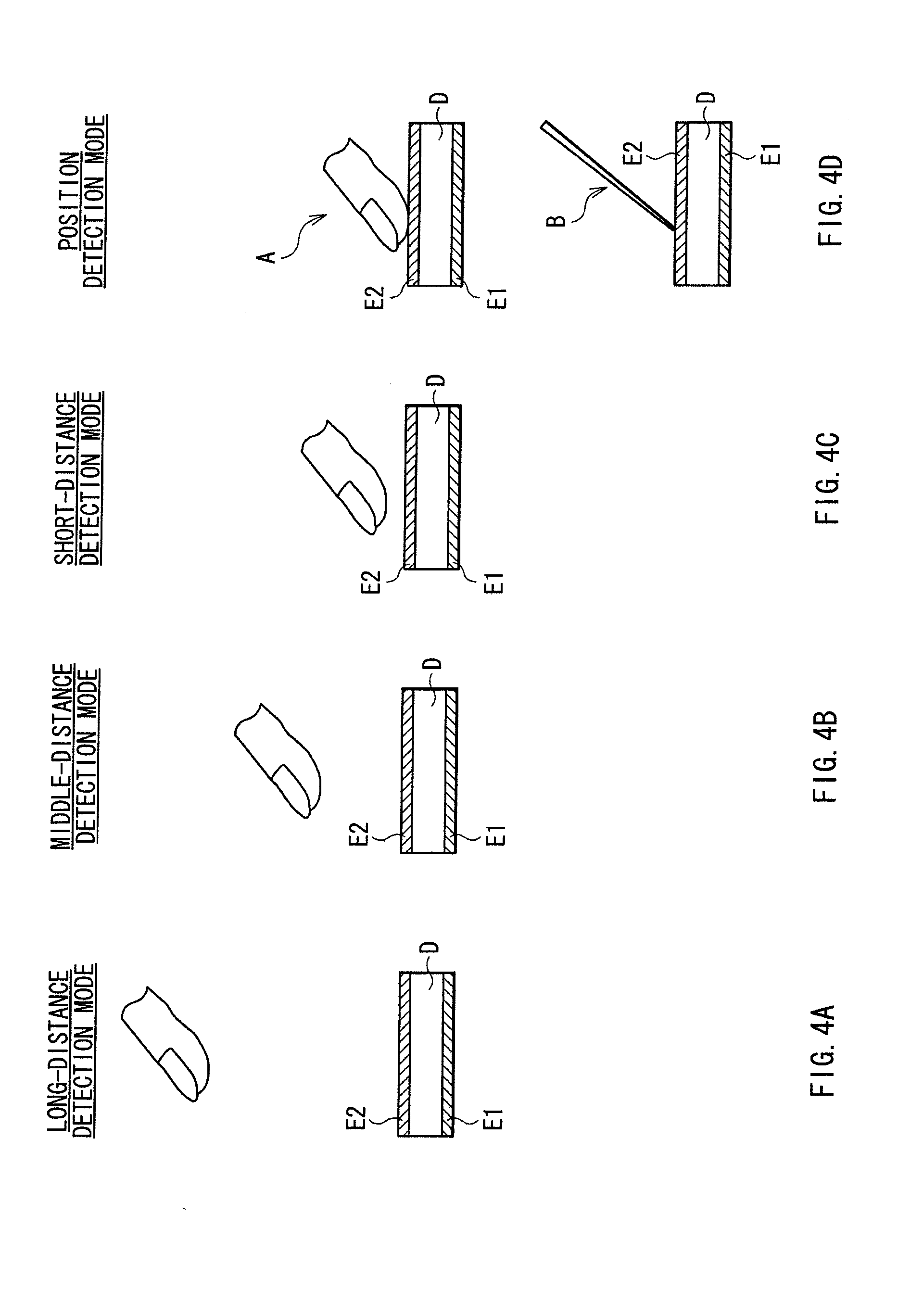
[0117]However, in the embodiment, among all electrode patterns of the sensor detection electrode 44, a selective number of effective electrode patterns is changed in each detection mode. Specifically, in the long-distance detection mode, one detection electrode pattern or a number close to one of the detection electrode patterns (here, two patterns disposed on outermost sides) of all the detection electrode patterns of the sensor detection electrode 44 are selected as effective electrode patterns 44A as shown in FIG. 13A. In contrast, in the position detection m...

third embodiment

[0129]FIGS. 15A to 15D schematically show inverted waveforms (AC square waves Sg) of a detection drive signal (Vcom2) according to a third embodiment of the invention in each of the detection modes. In the above embodiment, the selective number of the drive electrode patterns in line-sequential drive of the common electrode 43 is changed, or the selective number of the effective electrode patterns of the sensor detection electrode 44 is changed as a measure to change a range of an electric line of force. In the third embodiment, a drive signal Vcom2, which is applied to each drive electrode pattern in line-sequential drive of the common electrode 43, is changed. The embodiment, which is applied to a capacitance-type touch sensor similar to the display device 1A of the first embodiment, is described with, as an example, a case where gradual detection is performed from a long-distance detection mode to a position detection mode. Hereinafter, the same components as in the display devic...


PUM


Abstract

A touch sensor that may detect an object away from the sensor is provided. The touch sensor includes one or more drive electrodes; one or more detection electrodes forming capacitance in cooperation with the respective drive electrodes; a detection circuit applying drive signals to the respective drive electrodes to detect the object based on detection signals obtained from the respective detection electrodes in response to the respective drive signals; and a controller controlling to change a range of electric flux lines generated between the drive electrodes and the detection electrodes.

Description

[0001]The present application claims priority to Japanese Patent Application No. JP2009-155827 filed in the Japanese Patent Office on Jun. 30, 2009 and Japanese Patent Application No. JP 2010-050483 filed in the Japanese Patent Office on Mar. 8, 2010, the entire content of which is hereby incorporated by references.BACKGROUND OF THE INVENTION [0002]1. Field of the Invention[0003]The present invention relates to a display device such as liquid crystal display device, and particularly relates to a capacitance-type touch sensor that may be inputted with information by contact or approach of a user with a finger, and to a display device having such a touch sensor.[0004]2. Description of Related Art[0005]A display device is recently noticed, in which a contact detector, so-called touch panel, (hereinafter, called touch sensor) is directly attached onto a liquid crystal display device, and various button images are displayed on the liquid display device as a substitute for typical buttons...

Claims


Application Information

Patent Timeline
Patent Type & Authority Applications(United States)
IPC IPC(8): G06F3/045
CPCG06F3/044G02F1/13338G06F3/0416G06F3/0446G06F3/0412G06F2203/04106H03K17/962G06F2203/04101G06F2203/04108G09G3/3611
Inventor ISHIZAKI, KOJINOGUCHI, KOUJIHARADA, TSUTOMUTAKEUCHI, TAKEYAKIDA, YOSHITOSHINAKANISHI, TAKAYUKI
Owner JAPAN DISPLAY WEST
Why Eureka
Try Eureka