Lens-interchangeable camera and method of controlling the same
a technology of interchangeable lenses and camera bodies, which is applied in the field of lenses interchangeable cameras, can solve the problems of very low communication speed between the lens and the camera, high cost of creating a recovery filter every time the capturing conditions change, etc., and achieve the effect of reducing the amount of communication data and reducing the process load of filter creation
- Summary
- Abstract
- Description
- Claims
- Application Information
AI Technical Summary
Benefits of technology
Problems solved by technology
Method used
Image
Examples
first embodiment
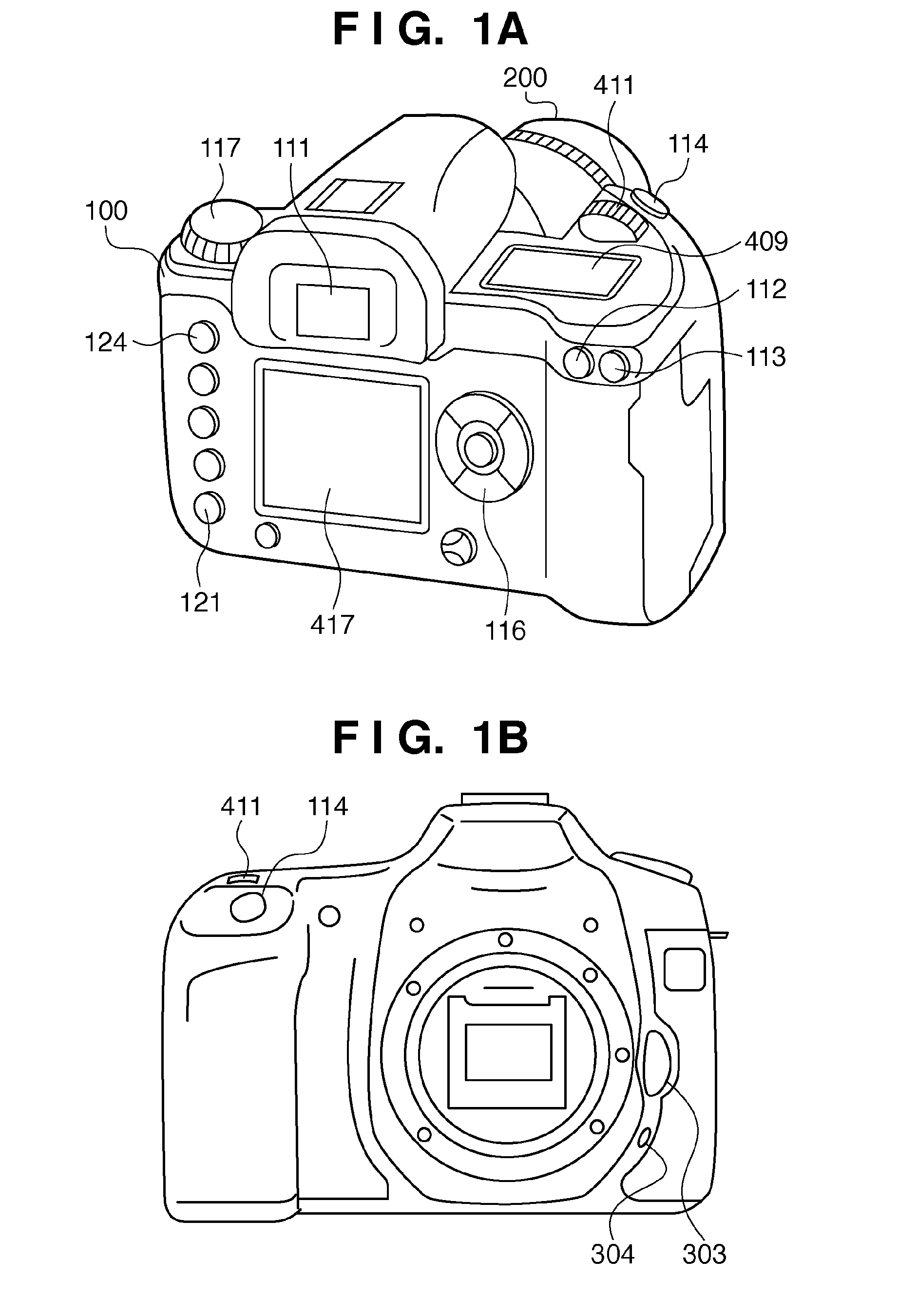
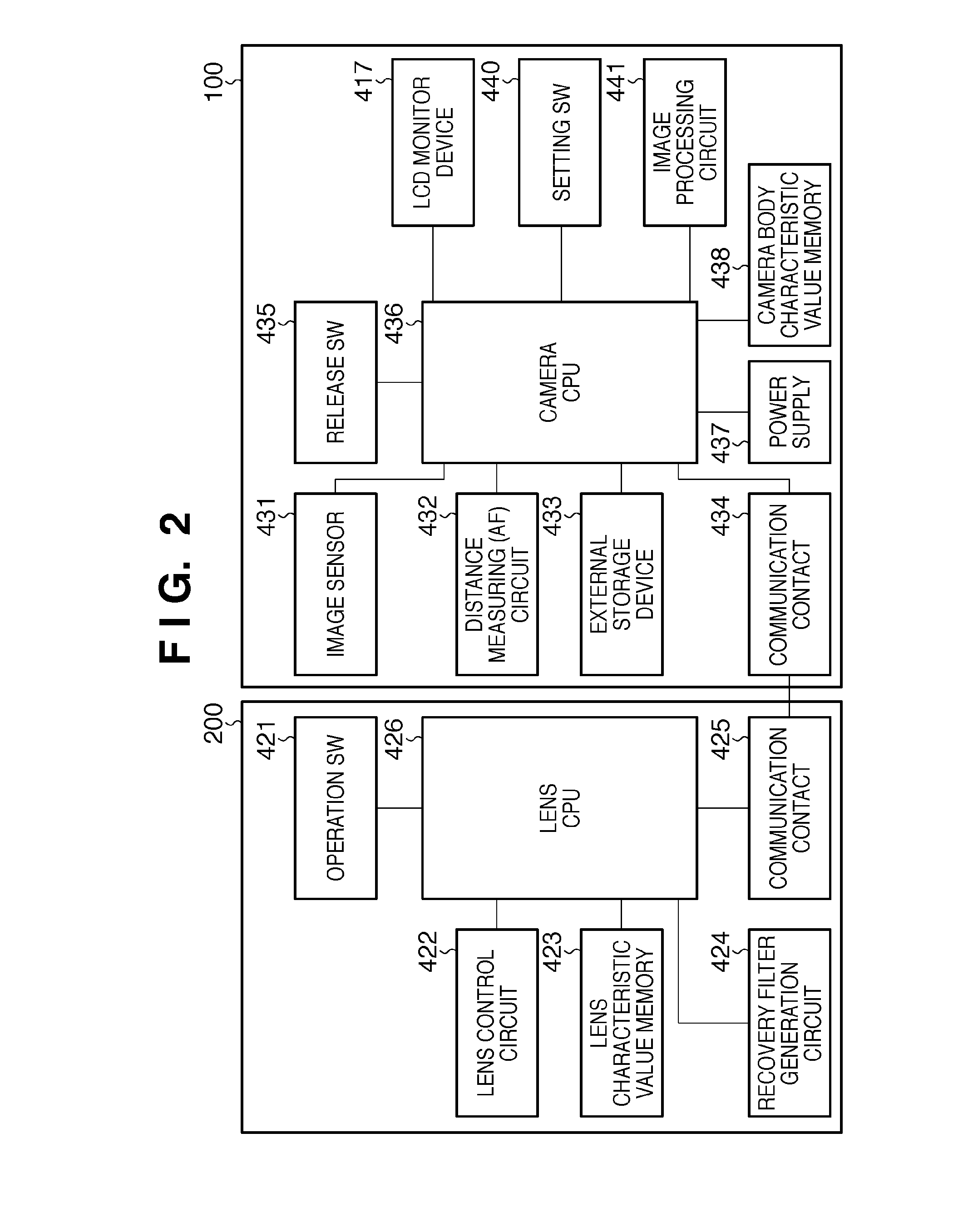
[0031]A lens-interchangeable camera according to this embodiment will be described with reference to FIGS. 1A, 1B, and 2. The lens-interchangeable camera can exchange the lens to be attached to it. In this embodiment, the camera is a digital camera.
[0032]Referring to FIG. 1A, a camera 100 includes, at its upper portion, an ocular window 111 for viewfinder observation, an AE (Automatic Exposure) lock button 112, an AF distance measuring point selection button 113, and a release button 114 for a capturing operation. The camera 100 also includes an electronic dial 411, capturing mode selection button 117, and external display device 409. The electronic dial 411 is a multi-function signal input device to be used, together with other operation buttons, to input a numerical value to the camera 100 or switch the capturing mode. The external display device 409 is formed from a liquid crystal display device to display capturing conditions (capturing parameters) such as a shutter speed, apert...
second embodiment
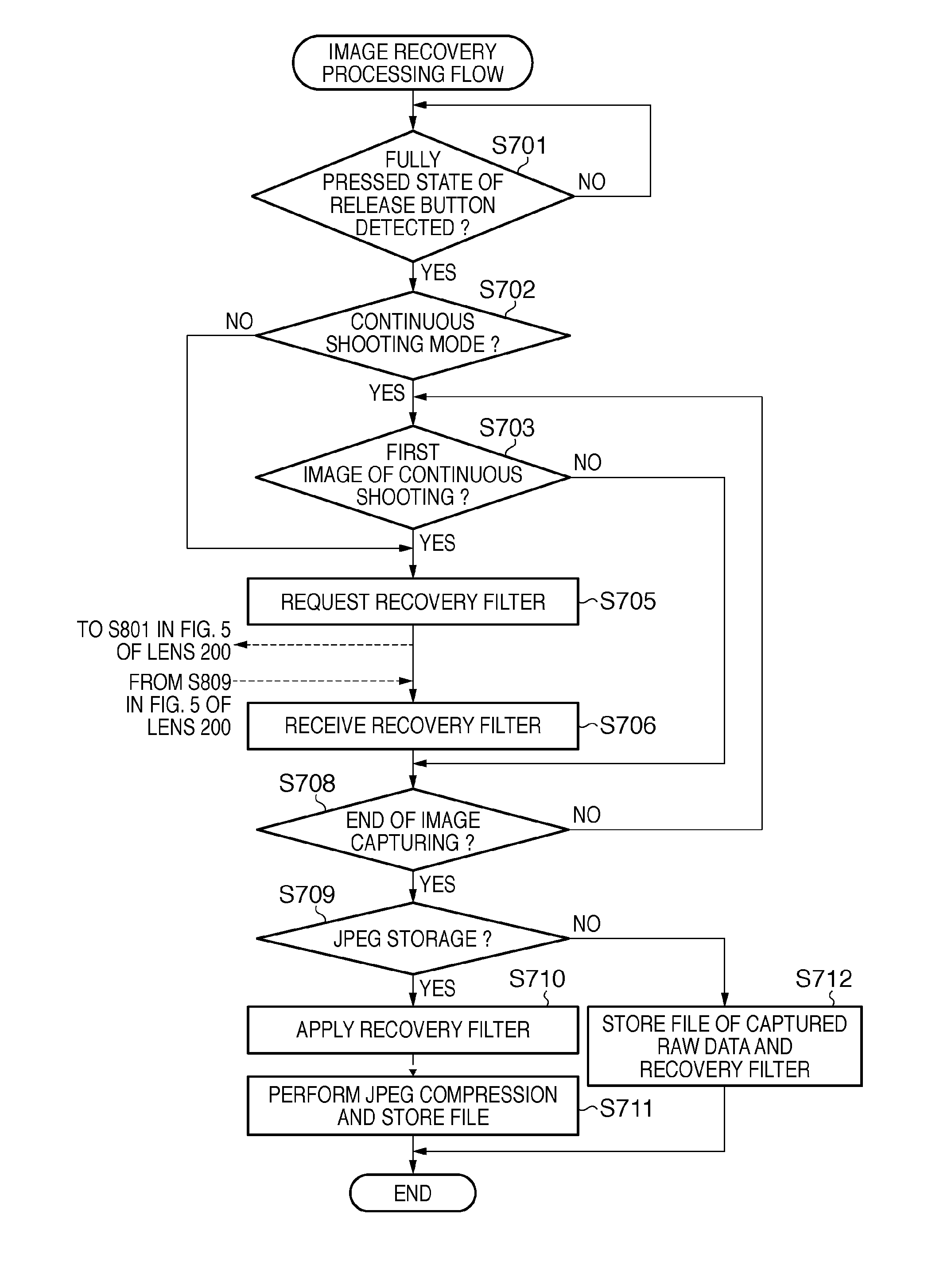
[0077]In the first embodiment, regarding that the capturing parameters of the first image and those of the second image captured by continuous shooting are almost the same, the number of times of recovery filter request can be reduced only in the continuous shooting mode. In this method, however, recovery filter request is done for the lens at least once every time continuous shooting is to be executed.
[0078]In the second embodiment, a cache memory for temporarily storing capturing parameters of previous time and recovery filters corresponding to them is provided in the camera. When the release button is pressed fully, the capturing parameters of previous time are compared with those of current time. Only when the difference falls outside an allowable range, the camera requests new recovery filters of the lens.
[0079]Processing to be performed by a camera 100 according to this embodiment will be described with reference to the flowchart of FIG. 6. Note that the same step numbers as i...
third embodiment
[0088]In the second embodiment, only the immediately preceding recovery filters and capturing parameters are held as a history. However, a camera 100 may hold recovery filters and capturing parameters of past few times as a history.
[0089]When storing a newly acquired recovery filter as a history, if the recovery filter storage area has no remaining capacity, several data in the recovery filter storage area need to be erased to store the newly acquired recovery filter.
[0090]For example, when a stop priority mode is set, the stop is fixed, and zoom is expected to frequently change. For this reason, recovery filters for the same aperture value are desired to leave as much as possible. In a shutter speed priority mode or continuous shooting mode, the stop is expected to change more frequently than zoom. Hence, recovery filters for the same zoom value are desired to leave as much as possible. In this embodiment, a method of updating stored data corresponding to a capturing mode when stor...
PUM
 Abstract
Description
Claims
Application Information
 - R&D
- Intellectual Property
- Life Sciences
- Materials
- Tech Scout
- Unparalleled Data Quality
- Higher Quality Content
- 60% Fewer Hallucinations
Browse by: Latest US Patents, China's latest patents, Technical Efficacy Thesaurus, Application Domain, Technology Topic, Popular Technical Reports.
© 2025 PatSnap. All rights reserved.Legal|Privacy policy|Modern Slavery Act Transparency Statement|Sitemap|About US| Contact US: help@patsnap.com


