Treatment device for operatively correcting defective vision of an eye, method for producing control data therefor and method for operatively correcting defective vision of an eye

a treatment device and eye technology, applied in the field of treatment devices for surgical correction of defective vision of the eye, can solve the problems of less safety and jeopardize the success of refractive therapy, and achieve the effects of reducing volume, improving optical quality, and improving overall optical quality of correction

Active Publication Date: 2010-12-30
CARL ZEISS MEDITEC AG
View PDF14 Cites 61 Cited by
  • Summary
  • Abstract
  • Description
  • Claims
  • Application Information

AI Technical Summary

Benefits of technology

[0021]The inventors have found that it is advantageous for the overall optical quality of the correction to remove more volume than is required per se, i.e. to provide a minimum thickness for the lenticule. Surprisingly, this contradiction to basically all surgical interventions, which try in the case of internal wounds to be as economical as possible with tissue, leads to a better optical quality, as there is no risk of tissue fragments in the cornea of the eye. The approach according to the invention therefore drastically reduces the need for postoperative corrections.
[0022]An embodiment of the invention additionally uses the minimum thickness to prevent that occurrence of in the FLEX method of postoperative (regression) problems occur due to detached and reapplied corneal lamella being disadvantageously inserted or being unable to rest smoothly at the edge of the removed volume. In order to avoid regression problems of this type, the invention provides a wide edge zone, thus producing for the corneal lamella, which merges there with the posterior cut face which was produced for isolating the lenticular volume, a transition zone causing almost no regression. If this transition zone is preferably also positioned outside the optically effective region, i.e. outside the dark-adapted pupil of the eye, the risk of further undesirable side effects is further reduced. Preferably, the transition zone has a width of between 0.1 and 1 mm.
[0023]It has further been found that regressions are particularly effectively reduced if the edge face opens as perpendicularly as possible into the anterior face. A course of this type is primarily surprising as, in the case of such perpendicular opening of the corneal lamella positioned here, even a step leading perpendicularly away from the anterior surface of the cornea can occur. This perpendicular opening on the one hand sets the minimum edge thickness and on the other hand has proven unproblematic with regard to regression if the edge face additionally has below this perpendicular opening a second portion, more inclined towards the axis of vision. As a result of this configuration, the lenticular volume has an edge thickness which is preferably between 5 and 50 μm. It has been found that an edge thickness of this type is unproblematic with regard to regression, but at the same time ensures that the piece of tissue can be removed more effectively, as the edge thickness prevents with sufficient certainty particles from becoming torn off from the edge when the piece of tissue is detached. Particles of this type influence the positioning of the corneal lamella after removal of the tissue much more intensively than does the comparatively lower edge thickness of the piece of tissue and thus the short, perpendicularly opening portion of the edge face. This configuration of the invention therefore takes an edge structure which at first sight appears negative and achieves therewith as a result lower regression, i.e. better ingrowth behaviour, than an edge which is as narrow as possible which would actually be expected.

Problems solved by technology

Tearing-up of the isolated volume would therefore be associated with major additional effort in the removal of a part of the isolated volume, is as a result also less safe and jeopardises the success of a refractive therapy.

Method used


Image

  • Treatment device for operatively correcting defective vision of an eye, method for producing control data therefor and method for operatively correcting defective vision of an eye
  • Treatment device for operatively correcting defective vision of an eye, method for producing control data therefor and method for operatively correcting defective vision of an eye
  • Treatment device for operatively correcting defective vision of an eye, method for producing control data therefor and method for operatively correcting defective vision of an eye

Examples


Embodiment Construction

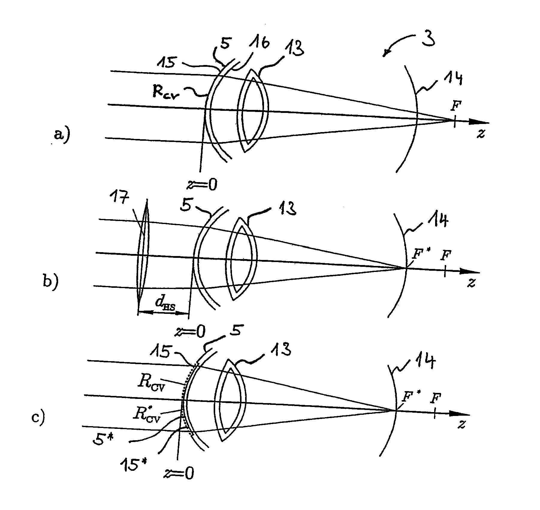
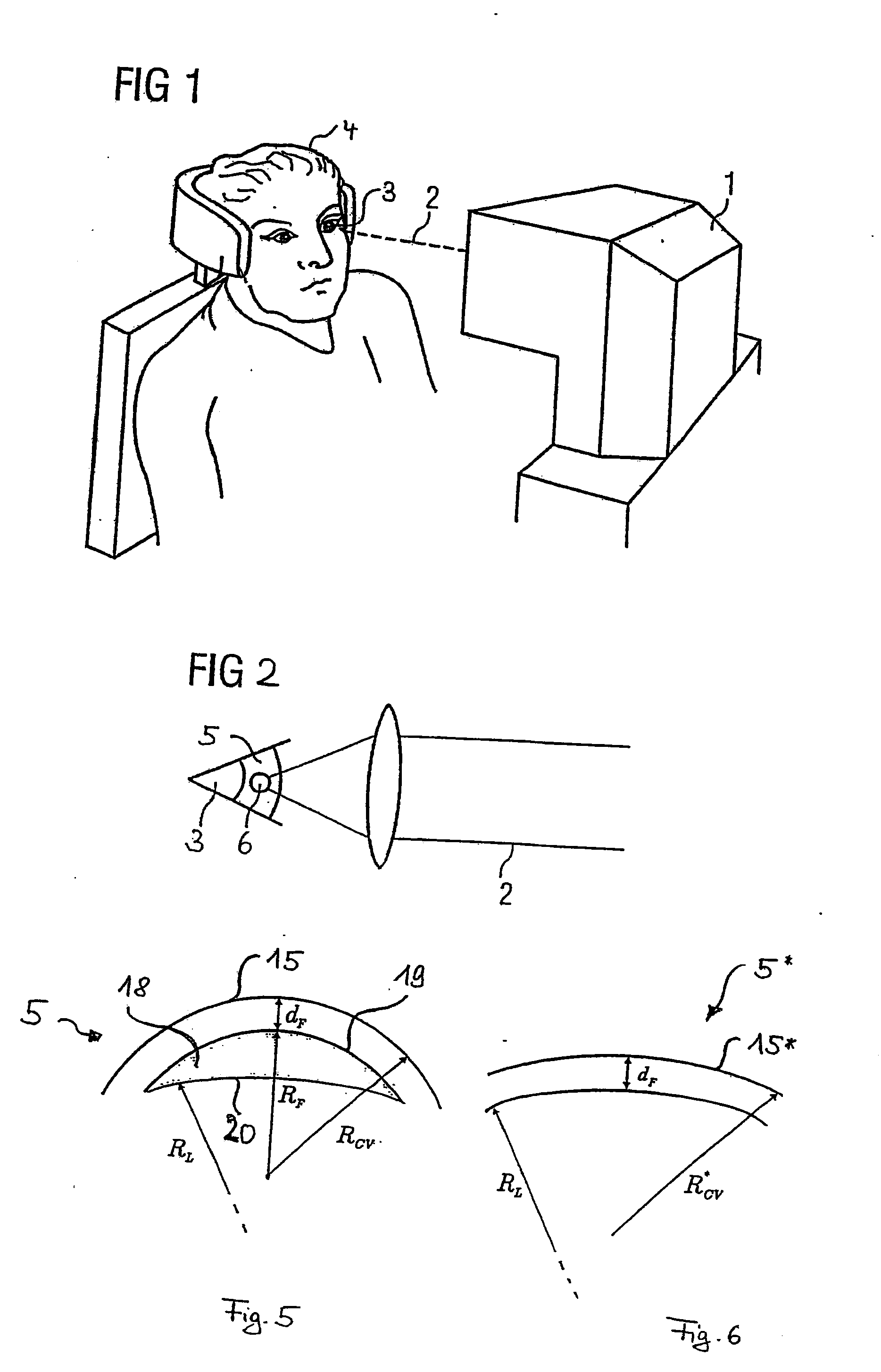
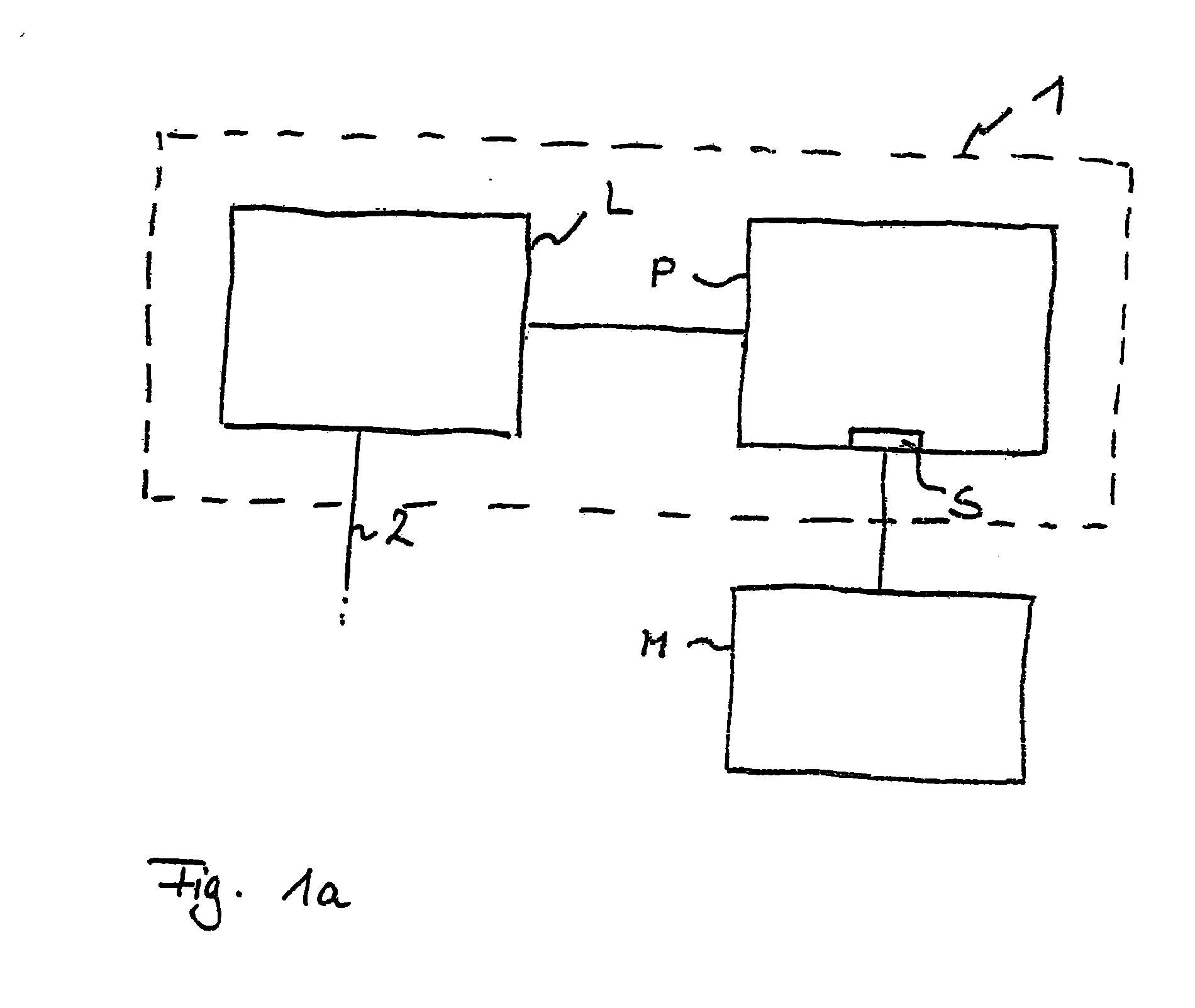
[0052]FIG. 1 shows a treatment device 1 for an ophthalmic surgical method similar to that described in EP 1159986 A1 or U.S. Pat. No. 5,549,632. The treatment device 1 effects a correction of defective vision in an eye 3 of a patient 4 by means of a treatment laser radiation 2. The defective vision may include hyperopia, myopia, presbyopia, astigmatism, mixed astigmatism (astigmatism involving hyperopia in one direction and myopia in a direction lying at right angles thereto), aspherical defects and higher-order aberrations. The treatment laser radiation 2 is applied in the described embodiment as a pulsed laser beam focused into the eye 3. The pulse duration is in this case in the femtosecond range, for example, and the laser radiation 2 acts by means of non-linear optical effects in the cornea. The laser beam has for example 50 to 800 fs-short laser pulses (preferably 100-400 fs) having a pulse repetition frequency of between 10 and 500 kHz. In the exemplary embodiment described, ...


PUM


Abstract

A treatment apparatus for operatively correcting myopia or hyperopia in an eye includes a laser device controlled by a control device and that separates the corneal tissue by applying a laser beam. The control device controls the laser device to emit the laser beam into the cornea such that a lenticule-shaped volume is isolated in the cornea. The control device, when controlling the laser device, predefines the lenticule-shaped volume such that the volume has a minimum thickness of between 5 and 50 μm. For myopia correction, the minimum thickness occurs on the edge of the volume, and for hyperopia correction the minimum thickness occurs in the region of the visual axis.

Description

PRIORITY CLAIM[0001]The present application is a National Phase entry of PCT Application No. PCT / EP2008 / 009247, filed Nov. 3, 2008, which claims priority from German Application Number 102007053281.6, filed Nov. 8, 2007, the disclosures of which are hereby incorporated by reference herein in their entirety.FIELD OF THE INVENTION[0002]The invention relates to a treatment apparatus for surgical correcting defective vision in the eye, the treatment apparatus having a laser device which is controlled by a control device and separates corneal tissue by applying laser radiation, the control device being adapted to control the laser device for emitting the laser radiation into the cornea in such a way that a lenticular volume is thus isolated in the cornea, the removal of which from the cornea effects the desired correction.[0003]The invention further relates to a method for generating control data for a laser device of a treatment apparatus for operatively correcting defective vision in t...

Claims


Application Information

Patent Timeline
Patent Type & Authority Applications(United States)
IPC IPC(8): A61F9/01
CPCA61B3/103A61F9/008A61F2009/00872A61F9/00827A61F9/00836A61F9/00804A61F2009/00855
Inventor BISCHOFF, MARKSTOBRAWA, GREGORBISSMANN, WILFRIED
Owner CARL ZEISS MEDITEC AG
Why Eureka
Try Eureka