
Counting device, physical quantity sensor, counting method, and physical quantity measuring method

Inactive Publication Date: 2010-12-30
YAMATAKE HONEYWELL CO LTD
View PDF18 Cites 13 Cited by
  • Summary
  • Abstract
  • Description
  • Claims
  • Application Information

AI Technical Summary

Benefits of technology

[0010]Accordingly, it is an illustrative aspect of the present invention to provide a counter and counting method wherein counting errors can be corrected even when there is continuous high-frequency noise present in the input to the counter, and to provide a physical quantity sensor and physical quantity measuring method capable of improving the measurement accuracy of the physical quantity by correcting MHP counting error.

Problems solved by technology

In the laser measuring device as set forth above, there are problems in that there would be errors in the numbers of MHPs counted by the counter due to, for example, noise, such as stray light, being counted as MHPs, or MHPs that are uncountable due to gaps in the signal, producing errors in the calculated physical quantities, such as distances.
However, the counter disclosed in JP '676 produces chattering, due to noise caused by higher frequencies rather than the MHPs, around the binarization threshold value in the signal inputted into the counter when the signal strength in measuring at a short distance is relatively strong as compared to the width of hysteresis.
This makes it impossible to properly correct the results of counting the MHPs, and thus there was a problem in that the results of counting the MHPs would be larger, for example, a few times as large, as the actual value.

Method used


Image

  • Counting device, physical quantity sensor, counting method, and physical quantity measuring method
  • Counting device, physical quantity sensor, counting method, and physical quantity measuring method
  • Counting device, physical quantity sensor, counting method, and physical quantity measuring method

Examples


Embodiment Construction

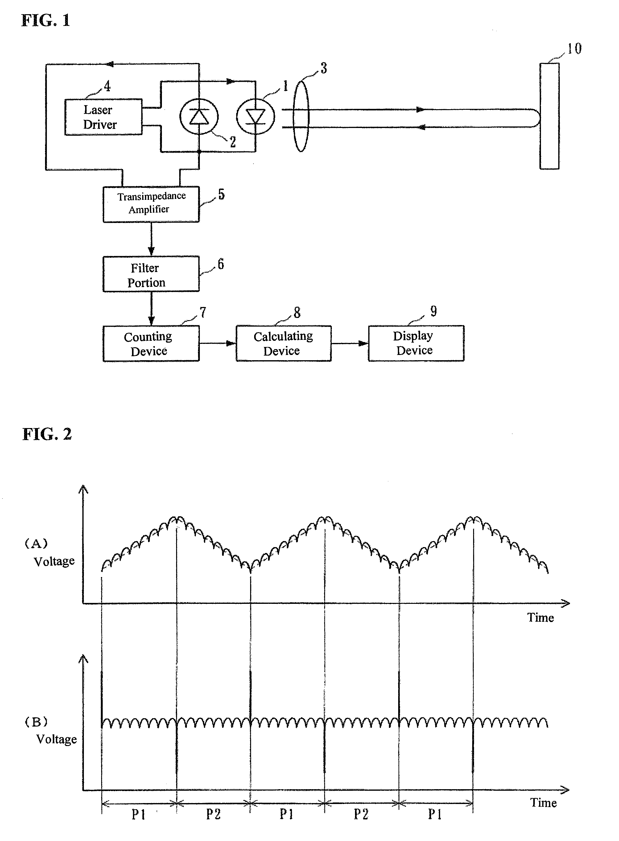
[0039]A form of embodiment of the present invention will be explained below in reference to the figures. FIG. 1 is a block diagram illustrating a structure for a vibration frequency measuring device that is one example of a physical quantity sensor relating to a form of embodiment according to the present invention.

[0040]The vibration frequency measuring device of FIG. 1 includes a semiconductor laser 1 for emitting a laser beam to the object 10 to be measured; a photodiode 2 for converting the optical output of the semiconductor laser 1 into an electric signal; a lens 3 for focusing and directing the beam from the semiconductor laser 1 and for focusing the light that is reflected from the object 10 to cause this light to be incident into the semiconductor laser 1; a laser driver 4 that serves as oscillation wavelength modulating unit for driving the semiconductor laser 1; a transimpedance amplifier 5 for converting into a voltage the current that is outputted from the photodiode 2,...


PUM


Abstract

A tension / speed measuring device comprises a laser driver for driving the oscillation of a semiconductor laser, and a counter for counting interference waveforms included in the output of a photodiode for converting the output of the semiconductor laser into an electrical signal. The counter measures the periods of interference waveforms during a measuring interval, where a frequency distribution for the periods of the interference waveforms during the measuring interval is generated from the measuring results, where a class value wherein the product of the class value and the frequency is a maximum is used as a representative value D0 at the periods of the interference waveform, to calculate a total Ns of the frequencies of the classes that are less than 0.5 times the representative value T0 and to calculate a total Nwn of the frequencies of the classes that are equal to or greater than (n+0.5) times the representative value T0 and less than (n+1.5) times the representative value T0, to correct the counting results based on these frequencies Ns and Nwn.

Description

CROSS REFERENCE TO RELATED APPLICATIONS[0001]The present application claims priority under 35 U.S.C. §119 to Japanese Patent Application No. 2009-153487, filed Jun. 29, 2009, which is incorporated herein by reference.FIELD OF TECHNOLOGY[0002]The present invention relates to a counter for counting a number of signals, and to an interference-type physical quantity sensor for calculating a physical quantity to be measured by measuring the number of interference waveforms using a counter.BACKGROUND OF THE INVENTION[0003]Conventionally there have been proposals for wavelength modulation-type laser measuring devices that use the self-coupling effect of semiconductor lasers. (See Japanese Unexamined Patent Application Publication 2006-313080 (“JP '080”).) The structure of this laser measuring device is illustrated in FIG. 22. The laser measuring device in FIG. 22 includes a semiconductor laser 201 for emitting a laser beam at an object 210; a photodiode 202 for converting, into an electric...

Claims


Application Information

Patent Timeline
IPC IPC(8): G01R23/16G06F19/00G01S17/34G01B9/02
CPCG01D5/266G01S17/325G01R23/16G01S17/34
Inventor UENO, TATSUYA
Owner YAMATAKE HONEYWELL CO LTD
Features
  • Generate Ideas
  • Intellectual Property
  • Life Sciences
  • Materials
  • Tech Scout
  • Unparalleled Data Quality
  • Higher Quality Content
  • 60% Fewer Hallucinations
Learn More