
Production method and production device of film having fine irregular pattern on surface

a production method and film technology, applied in the field of production methods and production apparatuses of films with fine irregular patterns on the surface, can solve the problems of general knowledge methods suffering problems, mold surface damage, mold release marks, etc., to reduce damage to the mold surface, excellent pattern surface, and reduce the formation of creases and undulations

Inactive Publication Date: 2011-01-06
TORAY IND INC
View PDF2 Cites 21 Cited by
  • Summary
  • Abstract
  • Description
  • Claims
  • Application Information

AI Technical Summary

Benefits of technology

The invention relates to a method for producing a film with a fine asperity pattern on its surface. The method involves peeling off a processed film from a mold surface and delivering it to a storage source. The method also includes a film holding means that holds the processed film and moves along the mold surface to prevent creases and a combination of a main roll and an auxiliary roll to hold the film and prevent undulation under heat load. The method allows for repeated production of the processed film with a predetermined length at a time. The invention also provides a film production method that prevents creases and undulation on the processed film and achieves a new predetermined length of the processing film without forming creases.

Problems solved by technology

This generally known method can suffer problems as described below.
In the peeling step, or the mold release step, therefore, depending on the characteristics of a film used or depletion of a mold releasing agent on a surface of a mold, the film can adhere to the mold surface to damage the mold surface, leaving flaws, or mold release marks, on a transfer surface of the film.
In addition, a film supplied onto a heated mold surface can soften in local portions at increased temperatures before being pressed against the surface of the transfer plate, and softened portions can be stretched under the tension applied to the film, leading to local undulation caused on the patterned surface.
Such local undulation can be caused significantly in low-rigidity or thin films.

Method used


Image

  • Production method and production device of film having  fine irregular pattern on surface
  • Production method and production device of film having  fine irregular pattern on surface
  • Production method and production device of film having  fine irregular pattern on surface

Examples


example 1

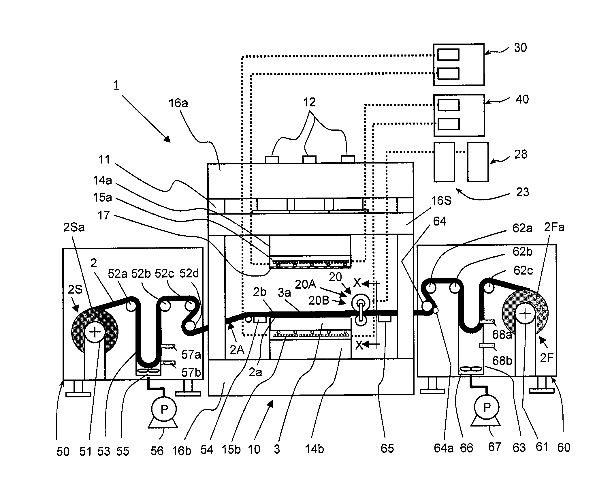
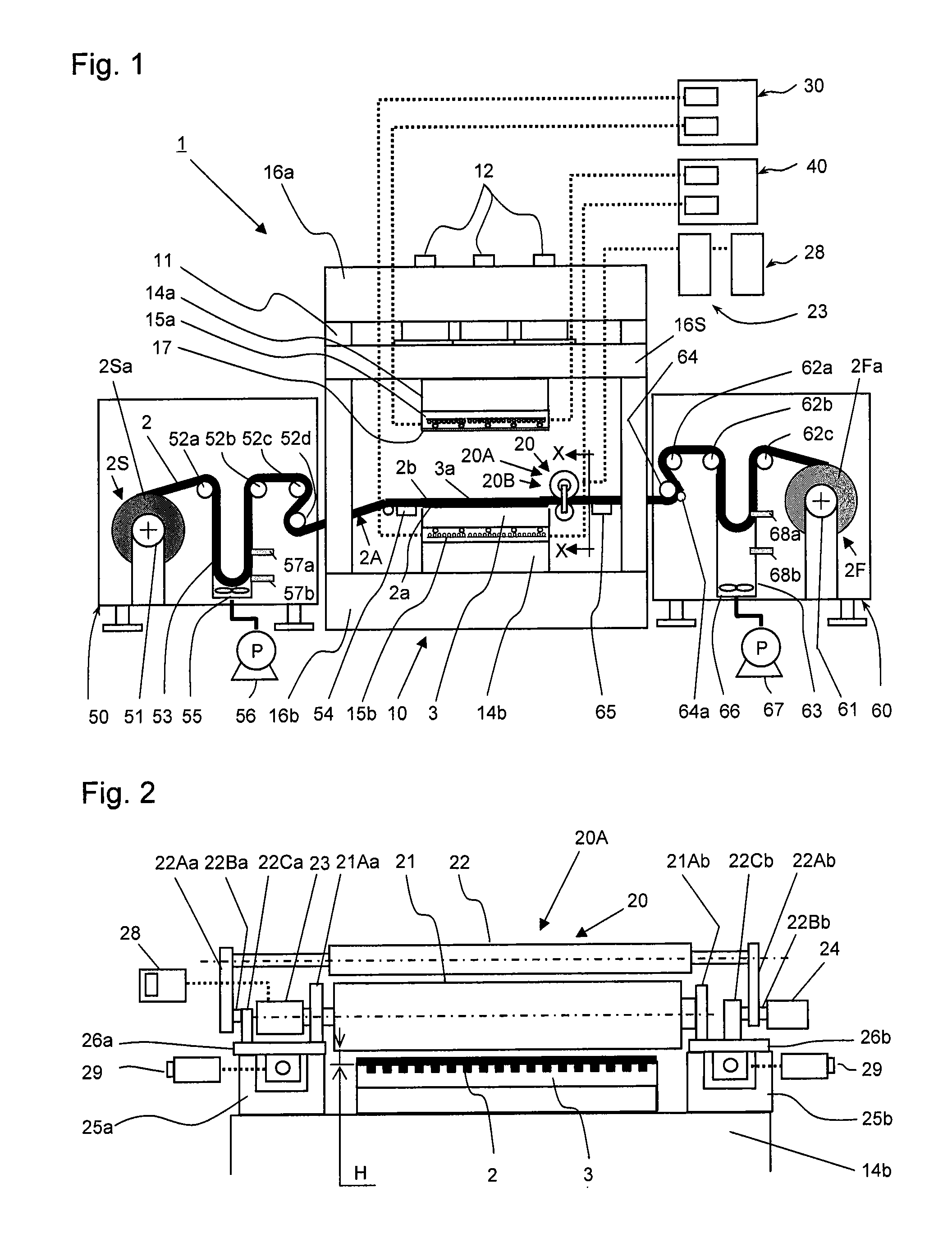
[0339]The film production apparatus 1 shown in FIG. 1 was used to produce a film having a fine asperity pattern.

[0340](1) The mold 3 used:

[0341]Size of the mold 3: 500 mm (in the width direction of the film 2)×800 mm (in the traveling direction of the film 2)×20 mm (thickness).

[0342]Material of the mold 3: copper

[0343]The fine asperity pattern formed on the mold surface 3a: many stripes arranged in the length direction the mold surface 3a with intervals in the width direction of the mold surface 3a. Each stripe has a right triangular cross section. The right triangle has a height of 10 μm and a base length of 5 μm. The bases of adjacent right triangles are located adjacent to each other.

[0344](2) The film pressing apparatus 10 used:

[0345]An oil hydraulic pressure pump having a maximum pressure load of 3,000 kN. Both the upper heat regulation plate 15a and the lower heat regulation plate 15b are made of an aluminum alloy with a size of 700 mm (in the width direction of the film 2)×1,...

example 2

[0357]The film production apparatus 401 shown in FIG. 4 was used to produce a film having a fine irregular pattern.

[0358](1) The mold 3 used: the same as in Example 1

[0359](2) The film pressing apparatus 10 used: the same as in Example 1

[0360](3) The film holding apparatus 20 used:

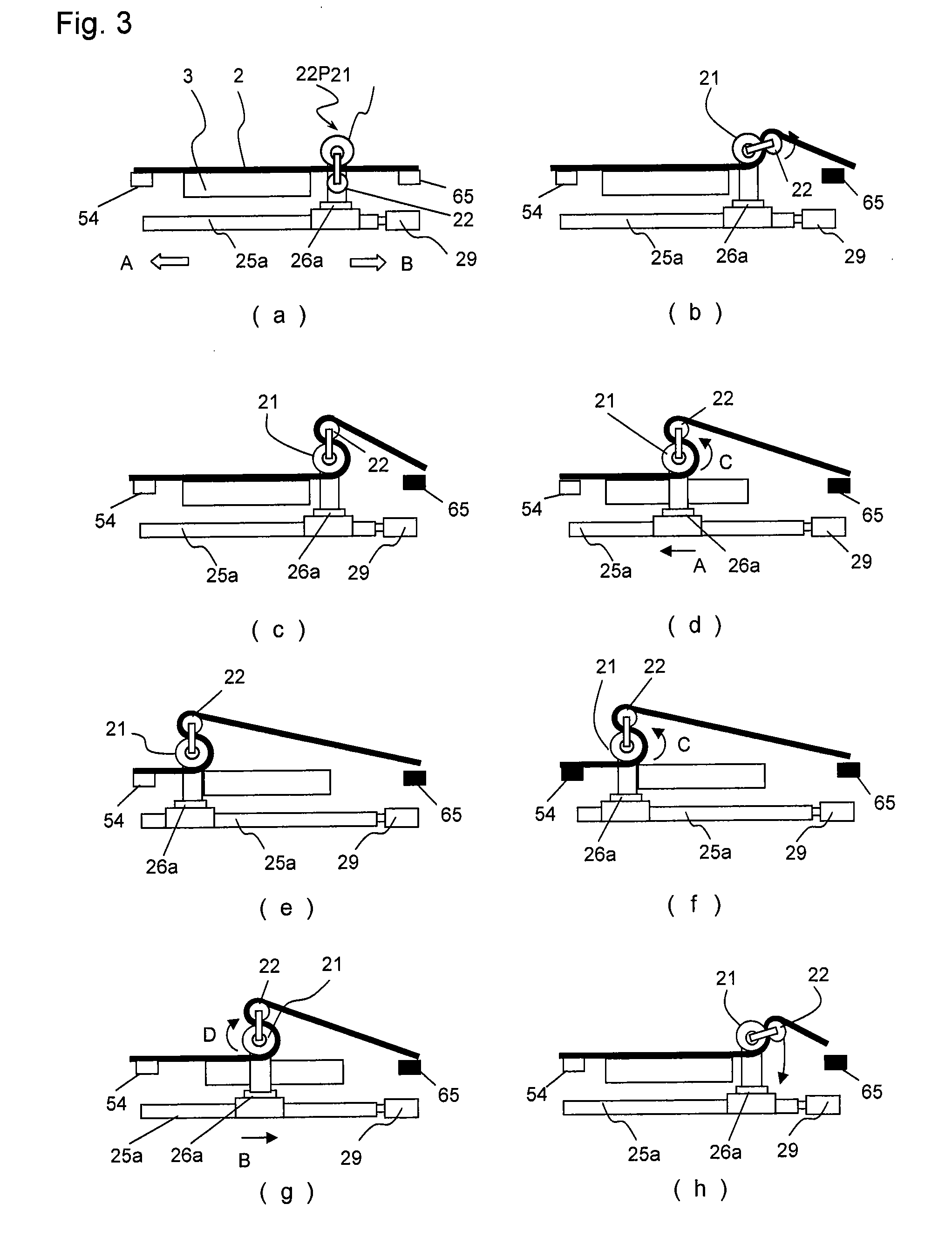
[0361]A combination of the main roll 21 and the auxiliary roll 22. The main roll 21 has an outside diameter of 150 mm. Its outermost layer is made of silicone rubber having a rubber hardness of 60 (JIS K6253), and the surface has a center line average roughness of 0.5 μm (JIS B0601). The main roll rotation driving means 23 is a servomotor. The auxiliary roll 22 has an outside diameter of 50 mm. Its outermost layer is made of fluorine resin. The distance (clearance H) between the main roll 21 and the mold surface 3a is 10 mm. The film holding apparatus movement driving means 29 for moving to and fro the film holding apparatus 20 including the main roll 21 and the auxiliary roll 22 over the mold surface 3a c...

example 3

[0371]The film production apparatus 401 shown in FIG. 4 was used to produce a film having a fine asperity pattern.

[0372](1) The mold 3 used: the same as in Example 1.

[0373](2) The pressing apparatus 10 used: the same as in Example 1.

[0374](3) The film holding apparatus 20 used: the same as in Example 2.

[0375](4) The crease formation prevention apparatus 420B used: the same as in Example 2.

[0376](5) The film 2 used: the same as in Example 1.

[0377](6) Actuation of major device elements used in the film production apparatus 401:

[0378]First, the film 2 was passed through the film transportation path 2A from the film take-out apparatus 50 to the film take-up apparatus 60 via the film pressing apparatus 10. Then, both the upper heat regulation plate 15a and the lower heat regulation plate 15b were heated up to a temperature of 120° C., and the upper heat regulation plate 15a was lowered to start pressing of the film 2. The pressing was implemented with a pressure of 5 MPa at the mold surf...


PUM

PropertyMeasurementUnit
flatnessaaaaaaaaaa
flatnessaaaaaaaaaa
pressureaaaaaaaaaa

Abstract

A method for producing a film having a fine irregular pattern intermittently includes feeding a film to be processed intermittently from upstream side to the vicinity of the surface of a die having a fine irregular pattern, transferring the pattern to the surface of the film by pressing the film against the surface of a die, stripping the processed film on which a pattern is formed from the surface of a die, and then feeding a new film to be processed to the die, wherein the processed film is stripped from the surface of a die by gripping and moving the processed film to the upstream side, and then the processed film is fed by a length of intermittent feed to the surface of a die while preventing the processed film from creasing.

Description

FIELD OF THE INVENTION[0001]The present invention relates to a production method and a production apparatus for a film having a fine asperity pattern on a surface thereof. Such a film having a fine irregular pattern on its surface is used as material for producing optical mediums or optical products.BACKGROUND OF THE INVENTION[0002]In a known method to produce an optical film for use as optical medium in light guide plates, light diffusion plates, lenses, etc., a film is pressed against a surface having a fine asperity pattern of an original plate to transfer the fine asperity pattern of the original plate onto a surface of the film. A long resin film is used as the film, and a portion having a predetermined length of the long film which is as a processing film is supplied intermittently onto a surface having a fine asperity pattern of a transfer plate (mold), and the processing film is pressed against the surface of the transfer plate to transfer the pattern to the surface of the p...

Claims


Application Information

Patent Timeline
Patent Type & Authority Applications(United States)
IPC IPC(8): B29C59/04
CPCB29C31/004B29C31/08B29C43/021B29C43/34B29C59/02B29L2011/00B29C2043/3422B29C2043/3602B29K2105/256B29C59/04B29K2883/005B29C2043/023
Inventor MINOURA, KIYOSHIHIRAI, YUMANOMURA, FUMIYASU
Owner TORAY IND INC
Learn More