Optical scanning apparatus and image forming apparatus using the same

a scanning apparatus and image technology, applied in the direction of electrographic process apparatus, instruments, printing, etc., can solve the problems of image deterioration, performance deterioration, and increase the sensitivity of the incident optical system, so as to reduce the field curvature

Inactive Publication Date: 2011-01-06
CANON KK
View PDF3 Cites 15 Cited by
  • Summary
  • Abstract
  • Description
  • Claims
  • Application Information

AI Technical Summary

Benefits of technology

[0016]It is an object of the present invention to provide an optical scanning apparatus and an image forming apparatus using the same, which are capable of reducing a field curvature in a main scanning direction, whi

Problems solved by technology

Thus, there is a problem of deterioration of an image.
This causes not only problems of upsizing of the entire apparatus and complication thereof but also problems that sensitivity of the incident optical system is increased, and hence a performance deterioration due to a manuf

Method used


Image

  • Optical scanning apparatus and image forming apparatus using the same
  • Optical scanning apparatus and image forming apparatus using the same
  • Optical scanning apparatus and image forming apparatus using the same

Examples


first embodiment

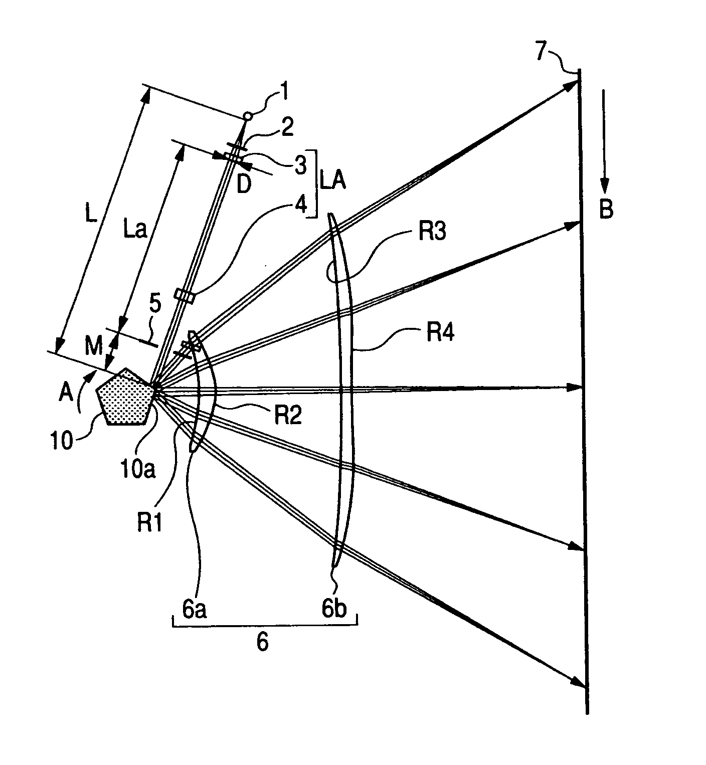
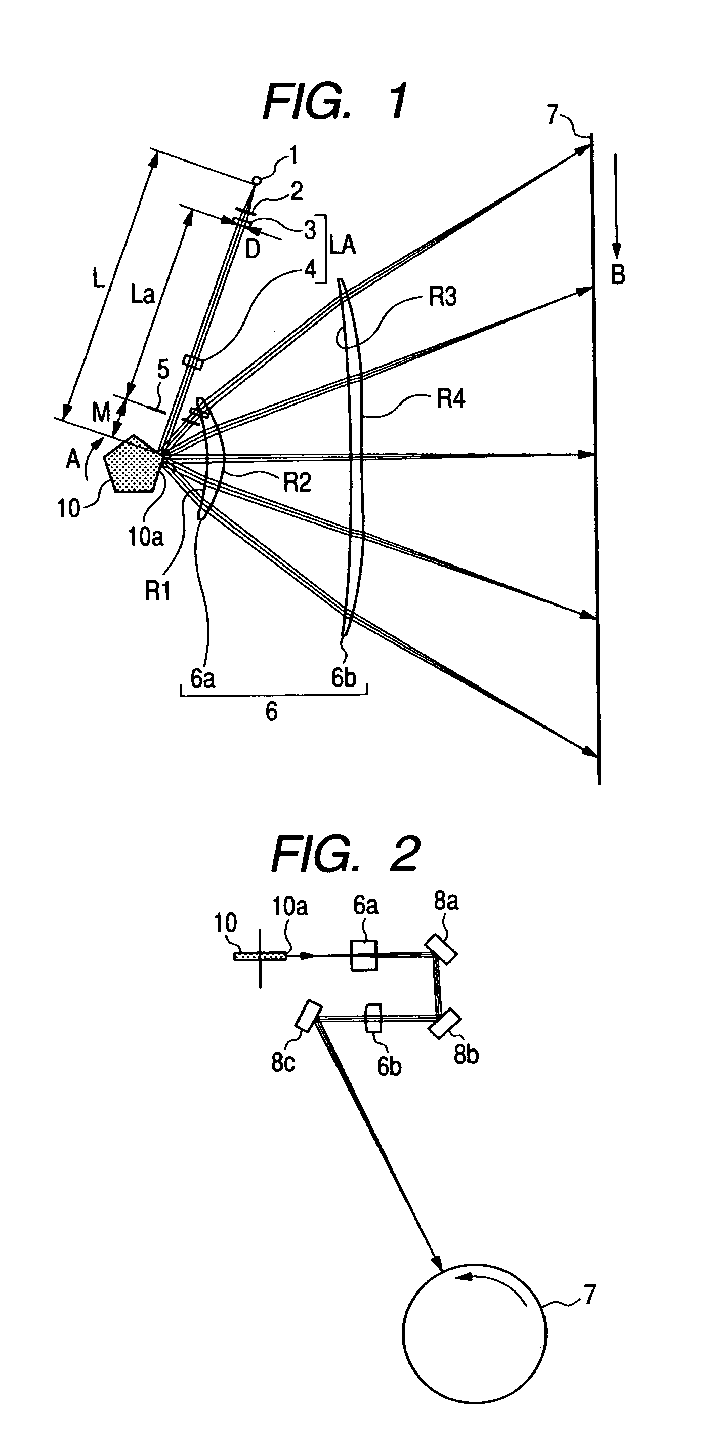
[0041]FIG. 1 is a main portion sectional view of a main scanning direction (main scanning sectional view) according to a first embodiment of the present invention. FIG. 2 is a main portion sectional view of a sub scanning direction (sub scanning sectional view) according to the first embodiment of the present invention.

[0042]It should be noted that, in the description below, the sub scanning direction (Z direction) is a direction parallel to a rotational axis of a deflection unit. A main scanning section is a section in which the sub scanning direction (direction parallel to the rotational axis of the deflection unit) is a normal line. A main scanning direction (Y direction) is a direction in which light fluxes deflected for scanning by a deflection surface of the deflection unit are projected on the main scanning section. A sub scanning section is a section in which the main scanning direction is a normal line.

[0043]In the diagram, a light source unit 1 includes a semiconductor las...

second embodiment

[0168]FIG. 7 illustrates a main scanning section of an incident optical system according to a second embodiment of the present invention. In FIG. 7, the element that is the same as the element illustrated in FIG. 1 is denoted by the same reference numeral.

[0169]The second embodiment is different from the first embodiment in that the collimator lens 13 is a spherical lens that is rotationally symmetrical to the optical axis, and a shape of the exit surface of the cylindrical lens 14 in the main scanning section is noncircular. Other structures and optical actions are the same as those of the first embodiment.

[0170]In other words, in FIG. 7, a collimator lens 13 serves as a first optical element, and is formed of a glass spherical lens that can be manufactured by grinding and is a sphere including an incident surface and an exit surface rotationally symmetrical to each other.

[0171]The plastic cylindrical lens 14 serving as the second optical element 14 works so that the light flux tha...

third embodiment

[0192]FIG. 10 illustrates a main scanning section of an incident optical system according to a third embodiment of the present invention. In FIG. 10, the element that is the same as the element illustrated in FIG. 1 is denoted by the same reference symbol.

[0193]Table 4 illustrates values of the incident optical system in this embodiment.

TABLE 4rdN(670 nm)Light source (light emitting point)0.00019.2610.0000Sub scanning aperture stop4.000Collimator lens100.0003.0001.5273−14.957*43.0000.0000Cylindrical lens0.0003.0001.52730.00034.0001.0000Main scanning aperture stop22.500Deflection surface0.0000.0001.0000Aspheric surface coefficientA0.00E+00B3.05E−05C−1.00E−07D0.00E+00E0.00E+00F0.00E+00G0.00E+00*Aspheric surface

[0194]The third embodiment is different from the first embodiment described above in that a collimator lens 73 is formed of a plastic mold lens and that the distance between the collimator lens 73 and the cylindrical lens 4 is decreased compared with the first embodiment. In add...


PUM


Abstract

Provided is an optical scanning apparatus has a plurality of light emitting portions and an incident optical system including optical element, wherein each shape of optical surfaces in a main scanning section of optical elements is formed into a noncircular shape. When defining that W is a space between specific light emitting portions farthest from an optical axis in the main scanning direction, La is an optical path length between an aperture stop and a specific optical surface closest to the light source unit among the noncircular optical surfaces of the incident optical system, f1 is a focal length of the incident optical system in the main scanning direction, and D is a light flux width in the main scanning direction of a light flux emitted from the specific light emitting portion in the main scanning direction on specific the optical surface, the equation 2D≧|W·La/2f1|≧D/8 is satisfied.

Description

BACKGROUND OF THE INVENTION[0001]1. Field of the Invention[0002]The present invention relates to an optical scanning apparatus and an image forming apparatus using the same. The present invention is suited to an image forming apparatus such as a laser beam printer, a digital copying machine, or a multi-function printer, which adopts an electrophotography process.[0003]2. Description of the Related Art[0004]Conventionally, in an optical scanning apparatus that is used for a laser beam printer or a digital copying machine, a light flux emitted from a light source unit is guided to a light deflecting device by an incident optical system.[0005]In such optical scanning apparatus, high speed and high resolution can be achieved by increasing the number of light emitting portions of the light source unit.[0006]There are conventionally proposed various optical scanning apparatuses that can achieve high speed and high resolution by increasing the number of light emitting portions of the light...

Claims


Application Information

Patent Timeline
IPC IPC(8): G03G15/041G02B26/08
CPCB41J2/471G02B13/0005H04N1/1135G03G15/0435G02B26/123
Inventor KUDO, GENICHIRO
Owner CANON KK
Why Eureka
Try Eureka