Wind turbine with pressure profile and method of making same

a technology of wind turbines and pressure profiles, which is applied in the field of wind turbines, can solve the problems of inefficient difficult transportation of tall towers and long blades, and inability to optimize the efficiency of wind turbines, etc., and achieve the effect of increasing productivity

Inactive Publication Date: 2011-01-06
FLODESIGN WIND TURBINE
View PDF51 Cites 13 Cited by
  • Summary
  • Abstract
  • Description
  • Claims
  • Application Information

AI Technical Summary

Benefits of technology

[0016]First-principles-based theoretical analysis of the preferred MEWT indicates that the MEWT can produce three or more times the power of its un-shrouded counterparts for the same frontal area, and increase the productivity, in the case of wind turbines, of wind farms by a factor of two or more.

Problems solved by technology

Although HAWTs have achieved widespread usage, their efficiency is not optimized.
Several problems are associated with HAWTs in both construction and operation.
The tall towers and long blades are difficult to transport.
Very tall and expensive cranes and skilled operators are needed for installation.
HAWTs are difficult to operate in near ground, turbulent winds.
Furthermore, ice build-up on the nacelle and the blades can cause power reduction and safety issues.
Their height also makes them obtrusively visible across large areas, disrupting the appearance of the landscape, which may be objectionable.
Finally, downwind variants suffer from fatigue and structural failure caused by turbulence.
This displacement requires a large amount of land for a wind farm, where several wind turbines are placed in a single location.

Method used


Image

  • Wind turbine with pressure profile and method of making same
  • Wind turbine with pressure profile and method of making same
  • Wind turbine with pressure profile and method of making same

Examples


Embodiment Construction

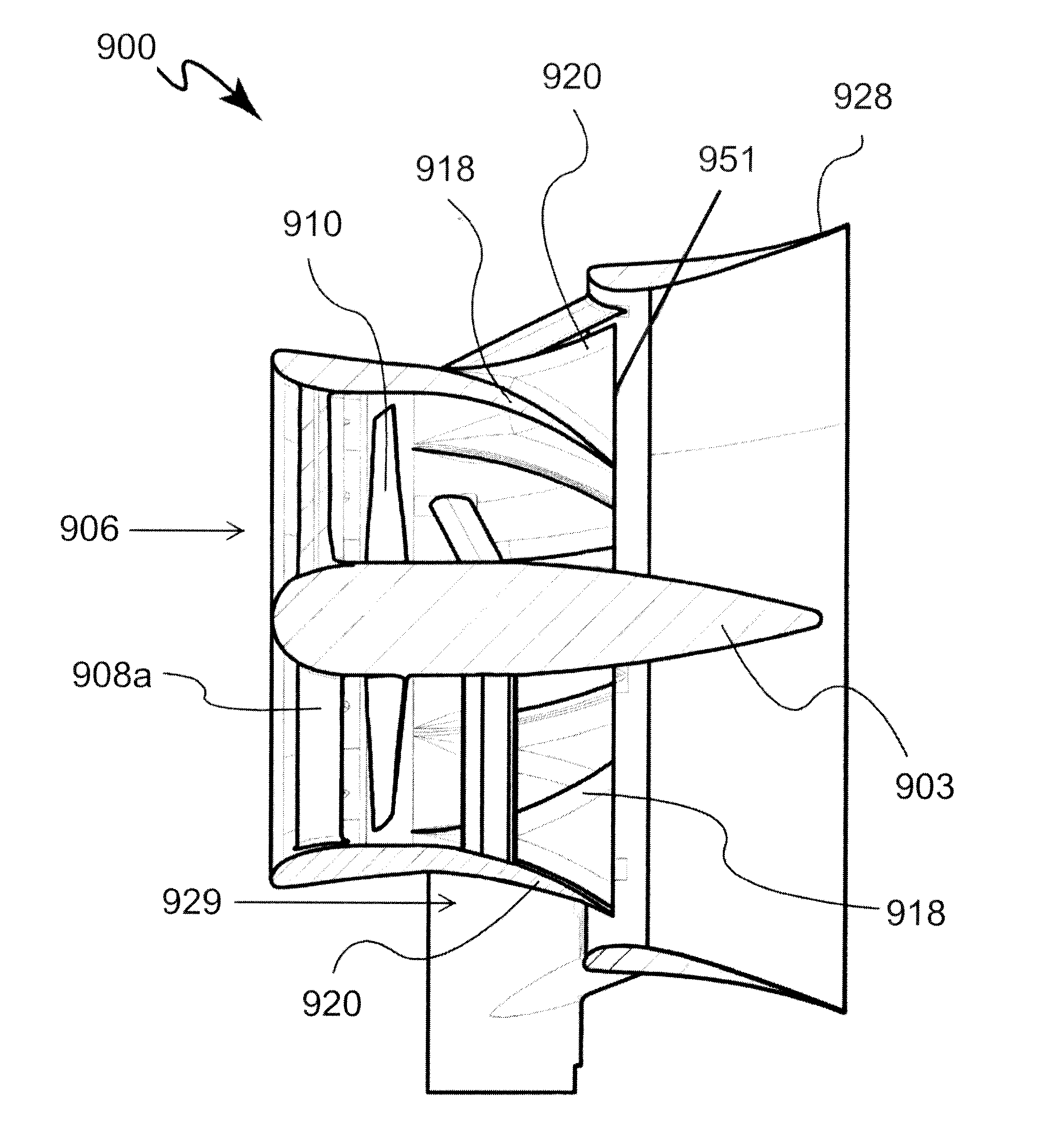
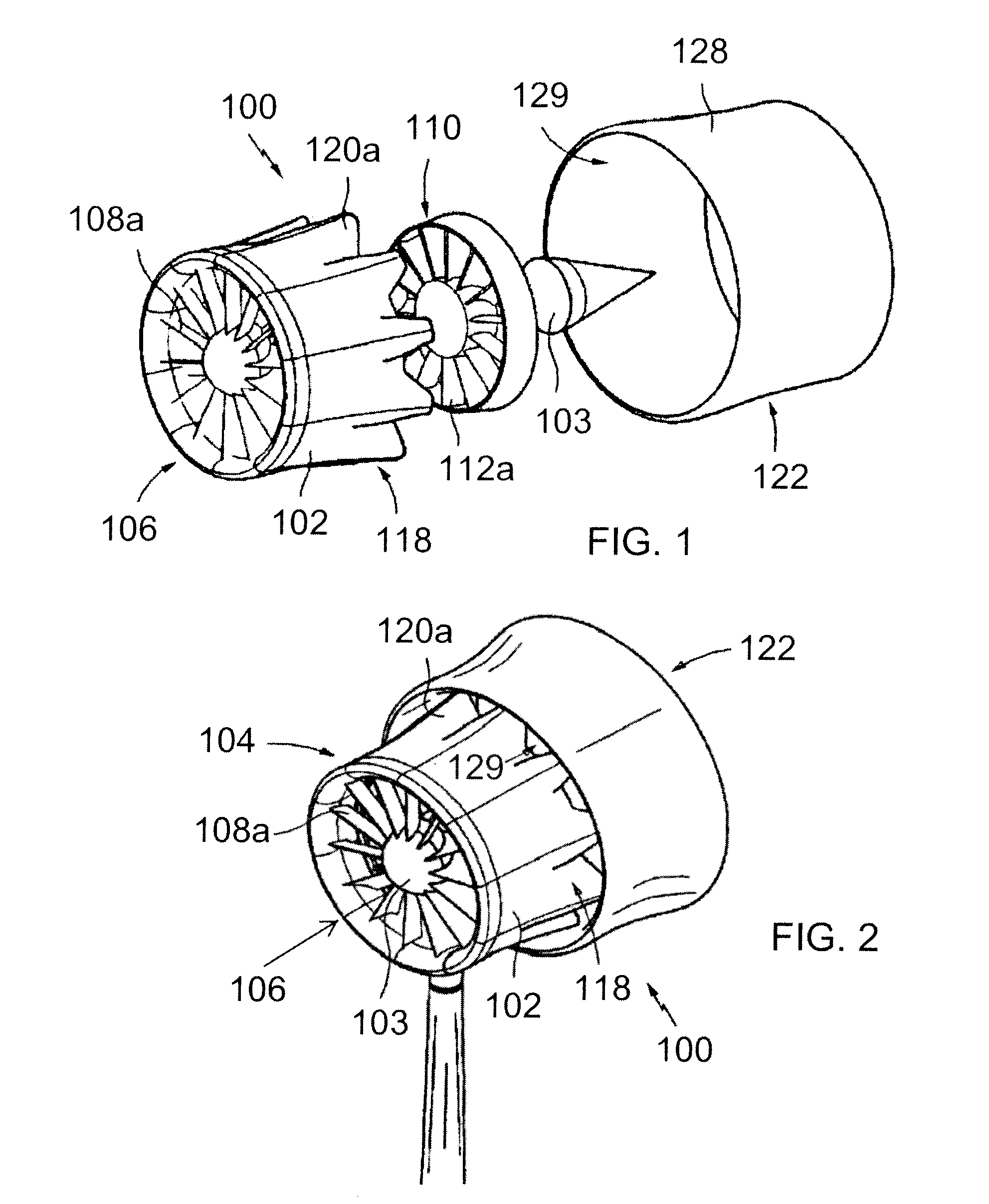
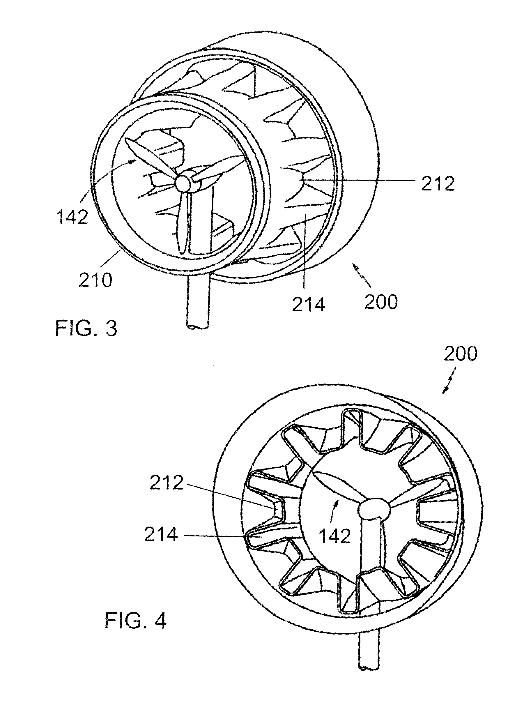
[0062]A more complete understanding of the components, processes, and apparatuses disclosed herein can be obtained by reference to the accompanying figures. These figures are merely schematic representations based on convenience and the ease of demonstrating the present development and are, therefore, not intended to indicate the relative size and dimensions of the devices or components thereof and / or to define or limit the scope of the exemplary embodiments.

[0063]Although specific terms are used in the following description for the sake of clarity, these terms are intended to refer only to the particular structure of the embodiments selected for illustration in the drawings and are not intended to define or limit the scope of the disclosure. In the drawings and the following description below, it is to be understood that like numeric designations refer to components of like function.

[0064]The modifier “about” used in connection with a quantity is inclusive of the stated value and h...


PUM

PropertyMeasurementUnit
pressureaaaaaaaaaa
pressureaaaaaaaaaa
pressureaaaaaaaaaa

Abstract

A wind turbine produces a unique pressure profile downstream of the wind turbine. This pressure profile reflects the structure of the wind turbine, which includes a shroud that has mixing lobes on a trailing edge thereof. The pressure profile includes high pressure and low pressure regions corresponding to the number and location of the mixing lobes on the shroud.

Description

[0001]This application is a continuation-in-part from U.S. patent application Ser. No. 12 / 054,050, filed Mar. 24, 2008, which claimed priority from U.S. Provisional Patent Application Ser. No. 60 / 919,588, filed Mar. 23, 2007. This application also claims priority to U.S. Provisional Patent Application Ser. No. 61 / 183,597, filed Jun. 3, 2009. Applicants hereby fully incorporate the disclosure of these applications by reference in their entirety.BACKGROUND[0002]The present disclosure relates to wind turbines, particularly shrouded wind turbines that produce a unique pressure profile downstream of the wind turbine.[0003]Conventional horizontal axis wind turbines (HAWTs) wind turbines have three blades and are oriented or pointed into the wind by computer controlled motors. These turbines typically require a supporting tower ranging from 60 to 90 meters in height. The blades generally rotate at a rotational speed of about 10 to 22 rpm. A gear box is commonly used to step up the speed to...

Claims


Application Information

Patent Timeline
Patent Type & Authority Applications(United States)
IPC IPC(8): F03D1/04F03D11/00B23P17/00
CPCF03D1/04F05B2240/13Y10T29/49245F05B2260/96Y02E10/72F05B2240/133Y02P70/50
Inventor PRESZ, JR., WALTER M.WERLE, MICHAEL J.KENNEDY, III, THOMAS J.KEELEY, WILLIAM SCOTTDOLD, ROBERTHICKEY, TIMOTHY
Owner FLODESIGN WIND TURBINE
Why Eureka
Try Eureka