If a user is approaching the edge of the range of the WiFi access point, the user will likely experience a low-speed link, and may be subject to periodic drop-outs if changes to the channel result in the
signal SNR dropping below
usable levels.
In an extreme situation where a WiFi access point is shared among a very large number of users,
throughput to each user can slow down to a crawl, and worse, data
throughput to each user may arrive in short bursts separated by long periods of no data
throughput at all, during which time other users are served.
This “choppy”
data delivery may impair certain applications, like media streaming.
But, beyond that, adding more WiFi base stations in the same coverage area will not increase aggregate throughput, since they will start sharing the same available spectrum among them, effectually utilizing time-division multiplexed access (TDMA) by “taking turns” using the spectrum.
For example, a user in a large
apartment building with a WiFi adapter may well experience very poor throughput due to dozens of other interfering WiFi networks (e.g. in other apartments) serving other users that are in the same coverage area, even if the user's access point is in the same room as the
client device accessing the
base station.
Although the link quality is likely good in that situation, the user would be receiving interference from neighbor WiFi adapters operating in the same
frequency band, reducing the effective throughput to the user.
Current multiuser
wireless systems, including both unlicensed spectrum, such as WiFi, and
licensed spectrum, suffer from several limitations.
However, these schemes can provide only up to 2× improvement in DL
data rate with four transmit antennas.
A key limitation of MU-
MIMO schemes in cellular networks is lack of spatial diversity at the transmit side.
In cellular systems employing MU-
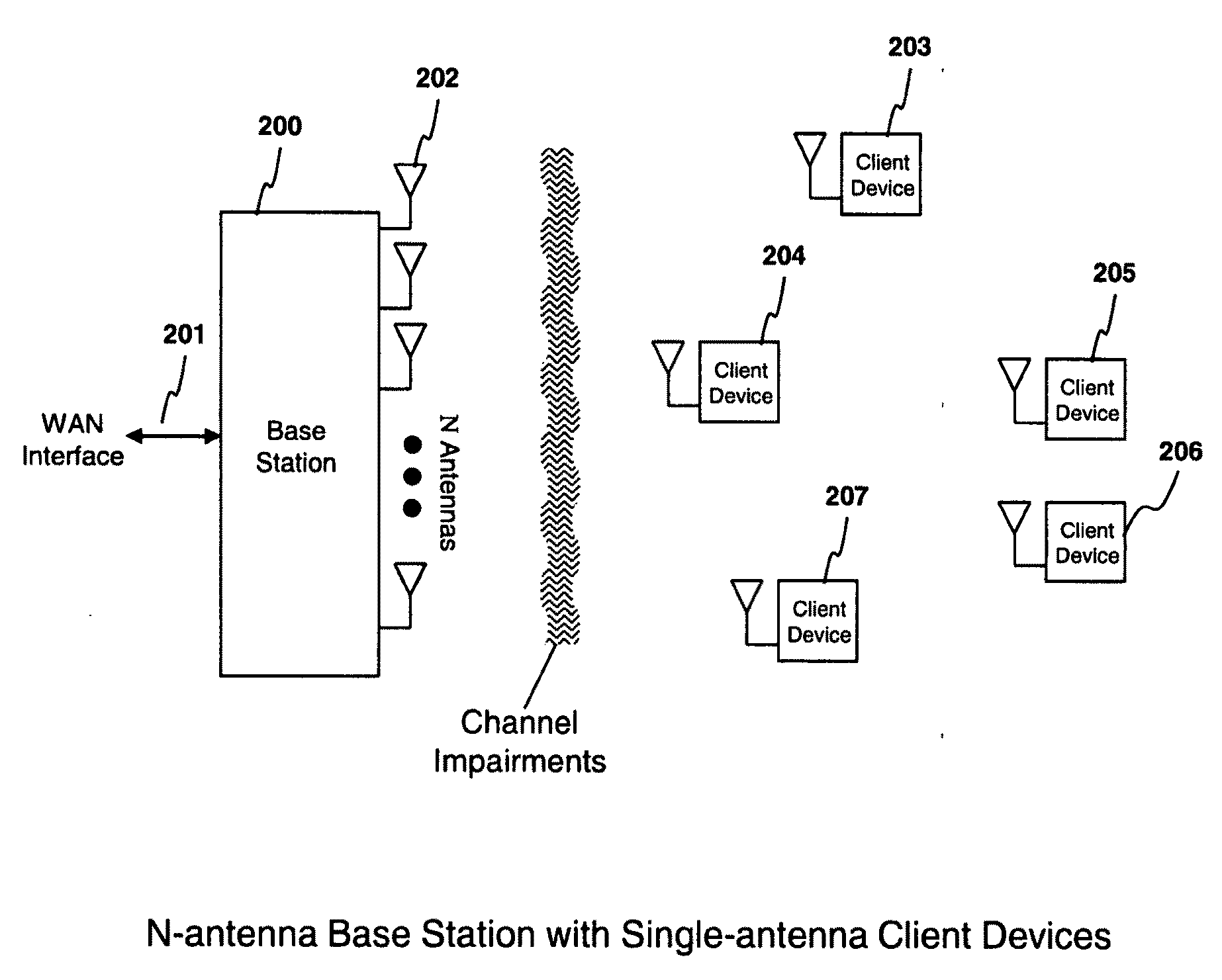
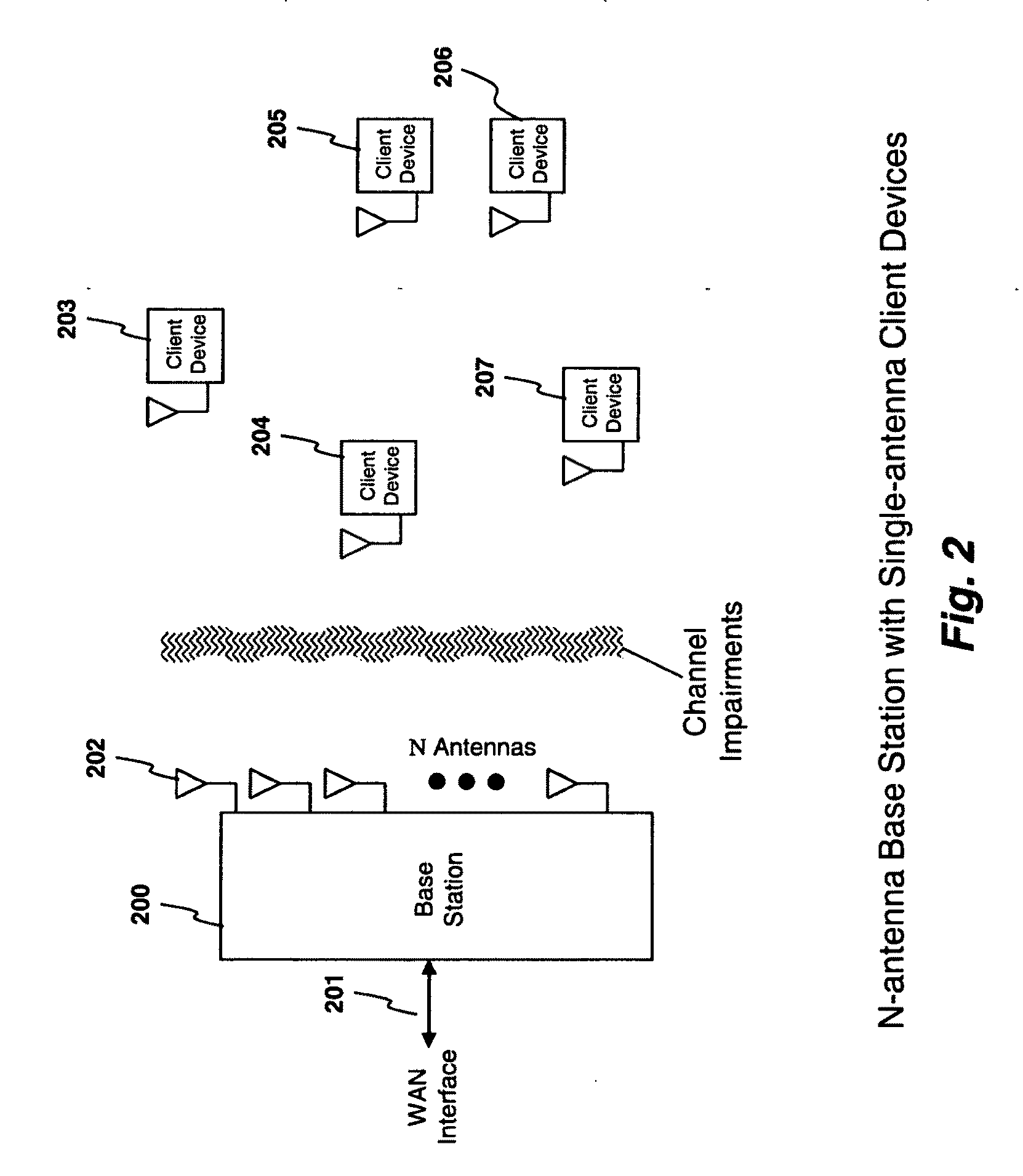
MIMO techniques, transmit antennas at a
base station are typically clustered together and placed only one or two wavelengths apart due to limited real estate on antenna support structures (referred to herein as “towers,” whether physically tall or not) and due to limitations on where towers may be located.
Other practical issues with cellular
system deployment include excessive cost and limited availability of locations for cellular antenna locations (e.g. due to municipal restrictions on antenna placement, cost of real-estate, physical obstructions, etc.) and the cost and / or availability of
network connectivity to the transmitters (referred to herein as “backhaul”).
Further, cellular systems often have difficulty reaching clients located deeply in buildings due to losses from walls, ceilings, floors, furniture and other impediments.
But, given that the cells and sectors of the cellular
system are typically in fixed locations, often dictated by where towers can be placed, even such limited benefits are difficult to
exploit if
user density (or
data rate demands) at a given time does not match up well with
tower / sector placement.
There are even further inefficiencies that result due to the fact that a given user's
data rate demands are typically independent of the user's location, but the available data rate varies depending on the link quality between the user and the
base station.
Since the data rate is typically shared among all of the users in a given cellular sector, the result of this is that all users are impacted by
high data rate demands from distant users with poor link quality (e.g. on the edge of a
cell) since such users will still demand the same amount of data rate, yet they will be consuming more of the
shared spectrum to get it.
Other proposed
spectrum sharing systems, such as that used by WiFi (e.g., 802.11b, g, and n) and those proposed by the White Spaces Coalition, share spectrum very inefficiently since simultaneous transmissions by base stations within range of a user result in interference, and as such, the systems utilize collision avoidance and sharing protocols.
These
spectrum sharing protocols are within the
time domain, and so, when there are a large number of interfering base stations and users, no matter how efficient each base
station itself is in spectrum utilization, collectively the base stations are limited to
time domain sharing of the spectrum among each other.
But, what is apparent by the fact that even advanced cellular systems can achieve only about a 3× increase in spectrum utilization compared to a single user utilizing the spectrum is that all of these techniques have done little to increase the
aggregate data rate among shared users for a given area of coverage.
In particular, as a given coverage area scales in terms of users, it becomes increasingly difficult to scale the available data rate within a given amount of spectrum to keep pace with the growth of users.
Such small cells can become extremely expensive given the limitations on where towers can be placed, and the requirement that towers must be placed in a fairly structured pattern so as to provide coverage with a minimum of “dead zones”, yet avoid interference between nearby cells using the same frequencies.
And, very often, there simply is no good solution, resulting in dead zones or inadequate
aggregate data rate capacity in a coverage area.
In other words, the rigid physical placement requirements of a cellular system to avoid interference among towers or base stations utilizing the same frequency results in significant difficulties and constraints in cellular system design, and often is unable to meet user data rate and coverage requirements.
And, as previously discussed, such prior art techniques (e.g. cellularization, sectorization) not only typically suffer from increasing the cost of the multi-user
wireless system and / or the flexibility of deployment, but they typically run into physical or practical limitations of aggregate throughput in a given coverage area.
For example, in a cellular system, there may not be enough available locations to install more base stations to create smaller cells.
And, in an MU-
MIMO system, given the clustered
antenna spacing at each base
station location, the limited spatial diversity results in asymptotically diminishing returns in throughput as more antennas are added to the base
station.
And further, in the case of multi-user
wireless systems where the user location and density is unpredictable, it results in unpredictable (with frequently abrupt changes) in throughput, which is inconvenient to the user and renders some applications (e.g. the delivery of services requiring predictable throughput) impractical or of low quality.
Thus, prior art multi-user
wireless systems still leave much to be desired in terms of their ability to provide predictable and / or high-quality services to users.
Or, to put it another way, it is taken as a given that if a user happens to receive transmissions from more than one base station or ad hoc
transceiver at the same time, the interference from the multiple simultaneous transmissions will result in a reduction of the SNR and / or bandwidth of the
signal to the user which, if severe enough, will result in loss of all or some of the potential data (or analog information) that would otherwise have been received by the user.
In short, all of these
spectrum sharing systems seek to address the limitation of multiuser
wireless systems that when multiple base stations and / or ad hoc transceivers transmitting simultaneously at the same frequency are received by the same user, the resulting interference reduces or destroys the data throughput to the affected user.
If a large percentage, or all, of the users in the multi-user wireless system are subject to interference from multiple base stations and / or ad hoc transceivers (e.g. in the event of the malfunction of a component of a multi-user wireless system), then it can result in a situation where the aggregate throughput of the multi-user wireless system is dramatically reduced, or even rendered non-functional.

