Position control method and robot

Active Publication Date: 2011-01-06
SEIKO EPSON CORP
View PDF17 Cites 90 Cited by
  • Summary
  • Abstract
  • Description
  • Claims
  • Application Information

AI Technical Summary

Benefits of technology

[0036]The driving signal of the step motor is a pulse waveform, and the driving shaft of the step motor is rotated in correspondence with the number of waves of the pulse waveforms. Accordingly, the movement amount of the movable portion can be controlled by controlling the driving signal of the step motor. A rotary encoder is not necessary for the step motor. However, there are cases where a step-out phenom

Problems solved by technology

While the robot hand vibrates, it is difficult for the robot hand to perform an operation such as an operation of gripping the work.
Then, when the driving time is long, the motor generates heat.
In a

Method used


Image

  • Position control method and robot
  • Position control method and robot
  • Position control method and robot

Examples


first embodiment

[0053]A robot according to this embodiment using a method of controlling the position of a robot hand as a characteristic will be described with reference to FIGS. 1A to 6B.

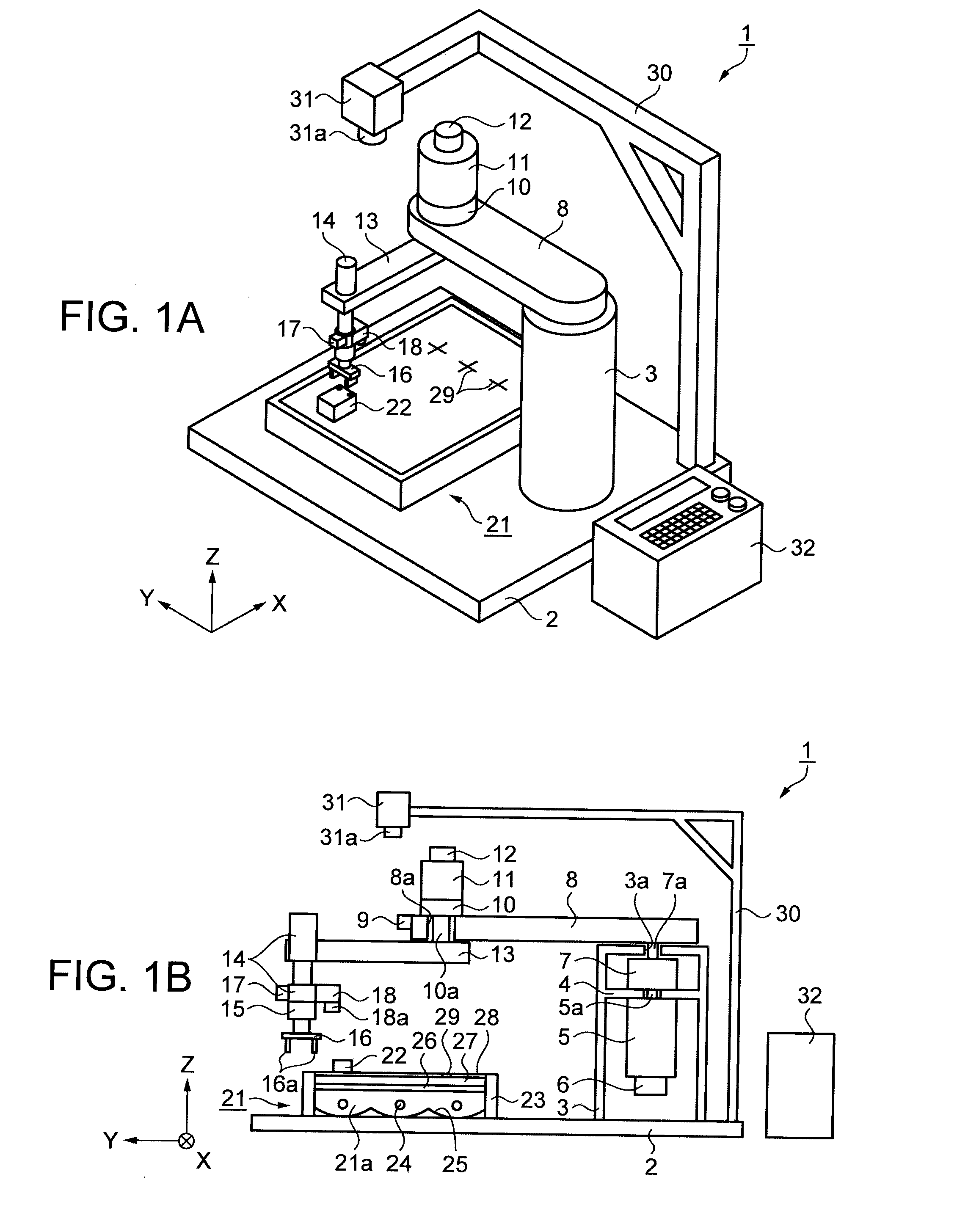
[0054]FIG. 1A is a schematic perspective view showing the configuration of the robot. FIG. 1B is a schematic cross-sectional view showing the configuration of the robot. As shown in FIGS. 1A and 1B, the robot 1 includes a base 2 that is formed to have a flat plate shape. One direction on a horizontal surface of the base 2 is assumed to be the X direction. In addition, the direction opposite to the direction of gravity is assumed to be the Z direction, and the direction that is perpendicular to the X direction and the Z direction is assumed to be the Y direction.

[0055]On the base 2, a support bar 3 is disposed. Inside the support bar 3, a hollow space is formed. This hollow space is vertically divided by a support plate 4. On the lower side of the support plate 4, a first motor 5 as a driving unit is disposed. On ...

second embodiment

[0119]Next, a robot according to an embodiment will be described with reference to FIG. 7. A difference between this embodiment and the first embodiment is that an elapsed time is used for the determination in the sensor switching determination process of Step S3 in this embodiment. Thus, the description of the same points as those of the first embodiment will be omitted, and only different points will be described. Other points are the same as those of the first embodiment.

[0120]FIG. 7 is a timing chart representing the transition of moving the hand portion to the target location. The vertical axis represents the hand portion-to-target distance 66 that is a distance between the hand portion 16 and the center of the work 22 as the target location. In the vertical axis, the upper side represents a location that is separated farther from the target location than the lower side. The horizontal axis represents the passing of time, and time progresses from the left side to the right side...

third embodiment

[0124]Next, a robot according to an embodiment will be described with reference to FIG. 8. A difference between this embodiment and the first embodiment is that the position of the hand portion 16 is detected by using a position detection sensor instead of the second imaging device 31. Thus, the description of the same points as those of the first embodiment will be omitted, and only different points will be described. Other points are the same as those of the first embodiment.

[0125]FIG. 8 is a schematic perspective view showing the configuration of the robot. As shown in FIG. 8, in the robot 76, support portions 77 that are formed longitudinally in the Z direction are disposed in three locations that are close to the periphery of the base 2. In addition, on the side of the support portion 77 in the Z direction, an ultrasonic receiver 78 is disposed. Furthermore, on the side of the elevation device 14 in the Z direction, an ultrasonic transmitter 80 is disposed. The robot 76 include...


PUM

PropertyMeasurementUnit
Shapeaaaaaaaaaa
Distanceaaaaaaaaaa

Abstract

A position control method for controlling a position of a movable portion, includes: performing control of allowing the movable portion to approach a predetermined position by moving the movable portion; and performing control of moving the movable portion to the predetermined position by moving the movable portion and detecting a relative position of the movable portion with respect to the predetermined position by using an imaging unit.

Description

BACKGROUND[0001]1. Technical Field[0002]The present invention relates to a position control method, and more particularly, to a control method for implementing high position precision.[0003]2. Related Art[0004]Robots having a joint link (hereinafter, referred to as an arm) of multiple joints are used in apparatuses having many assembled devices or the like. When such robots move the arm and stop the arm, the arm vibrates. While the arm vibrates, a robot hand that is disposed on the tip end of the arm also vibrates. While the robot hand vibrates, it is difficult for the robot hand to perform an operation such as an operation of gripping the work. Accordingly, the operation needs to wait for the vibration of the robot hand to stop.[0005]In order to improve the productivity of the robots, a method of shortening a vibration time of the robot hand is disclosed in Japanese Patent No. 3,883,544. According to the method, an angle sensor that detects the rotation angle of the arm is disposed...

Claims


Application Information

Patent Timeline
IPC IPC(8): B25J9/18B25J19/02G05D3/00G05D19/02
CPCB25J9/1638B25J9/1697G05B19/404G05B2219/39199G05B2219/40549G05B2219/41117Y10T156/19G05B2219/41123G05B2219/41168B25J9/1694B25J9/10B25J19/04G05B2219/41122B25J9/12Y10S901/09
Inventor IIDA, IZUMI
Owner SEIKO EPSON CORP
Why Eureka
Try Eureka