Photovoltaic Power Generating System

a photovoltaic power generation and photovoltaic technology, applied in the direction of pv power plants, heat collector mounting/support, light and heating equipment, etc., can solve the problems of deterioration of strength, easy bending of modules, and easy breakage so as to reduce the maximum absolute value of bending moment of solar cell modules, reduce the effect of power generating efficiency and increase the load-carrying capacity of photovoltaic power generating systems

Inactive Publication Date: 2011-01-13
KYOCERA CORP
View PDF5 Cites 6 Cited by
  • Summary
  • Abstract
  • Description
  • Claims
  • Application Information

AI Technical Summary

Benefits of technology

[0010]According to the photovoltaic power generating system, the supporting member is disposed at a position where it can abut against the solar cell module that is bent by a positive pressure load. Therefore, the maximum absolute value of the bending moment of the solar cell module can be reduced as compared with a case where the supporting member is disposed such that it is in contact with the solar cell module, and the load-carrying capacity of the photovoltaic power generating system can be increased.
[0011]Further, ventilation can be secured by the gap between the solar cell module and the supporting member. According to this, the solar cell module can be cooled and reduction in power generating efficiency can be suppressed.

Problems solved by technology

However, these proposals may cause deterioration of the strength.
For example, since the solar cell module of frameless structure has low rigidity, the module easily bends, and the solar cell module is easily broken.
Therefore, like the case of the solar cell module of frameless structure, a bending amount of a light-receiving surface of the solar cell module is increased, a transparent substrate easily falls off, and a crack is easily produced in the solar cell element.
That is, a radius of curvature of the solar cell module surface becomes small and abrupt bending is produced.
If the radius of curvature becomes smaller than a certain limit value, the solar cell module is broken due to a fracture of the transparent substrate, a crack of the solar cell element or the like.
Further, since the solar cell module and the supporting member axe in a state where they abut against each other, there is a problem that flow (ventilation) of air along a back surface of the solar cell module is hindered, and heat of the solar cell module cannot be sufficiently radiated.
There is an adverse possibility that water such as rain water is remained in the abutted part.
In this case, there is an adverse possibility that the back surface protection material used for the solar cell module is deteriorated due to remain of water for a long time.
If water permeates through the back surface protection material, ethylene vinyl acetate (EVA) that is used as filler for sealing the solar cell element absorbs water to generate acetic acid, and there is an adverse possibility that a wiring member is damaged.

Method used


Image

  • Photovoltaic Power Generating System
  • Photovoltaic Power Generating System
  • Photovoltaic Power Generating System

Examples


first embodiment

[0028]

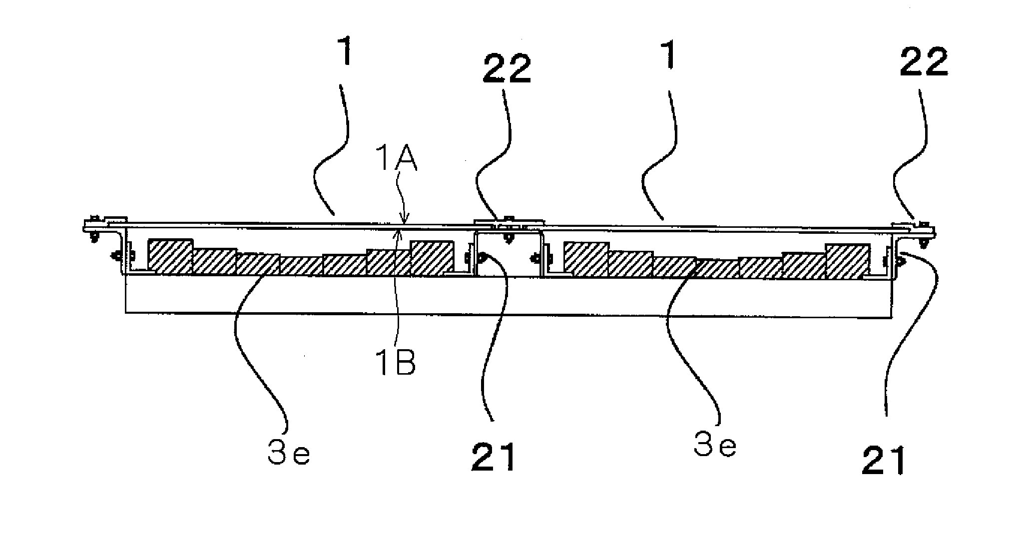
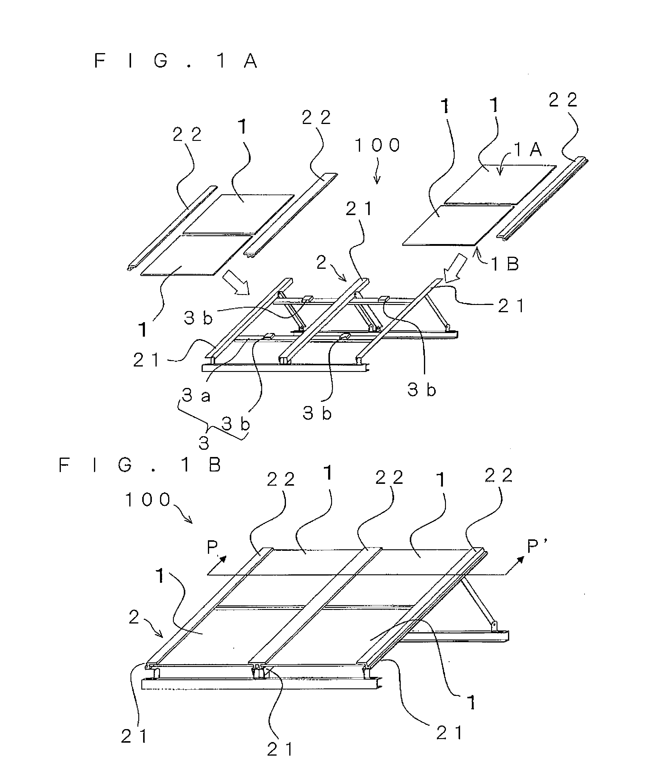
[0029]As shown in FIG. 1, a photovoltaic power generating system 100 generally includes solar cell modules 1, an installation platform 2, and supporting member 3. It is only necessary that the installation platform 2 holds a pair of ends (ends of opposed sides) of the solar cell modules 1 and for example, the installation platform 2 includes a plurality of holding members 21, and a plurality of locking members 22 that sandwich and fix the ends of the solar cell modules 1 together with holding members 21. The supporting member 3 is provided on the side of a non-light-receiving surface of the solar cell module 1.

[0030]

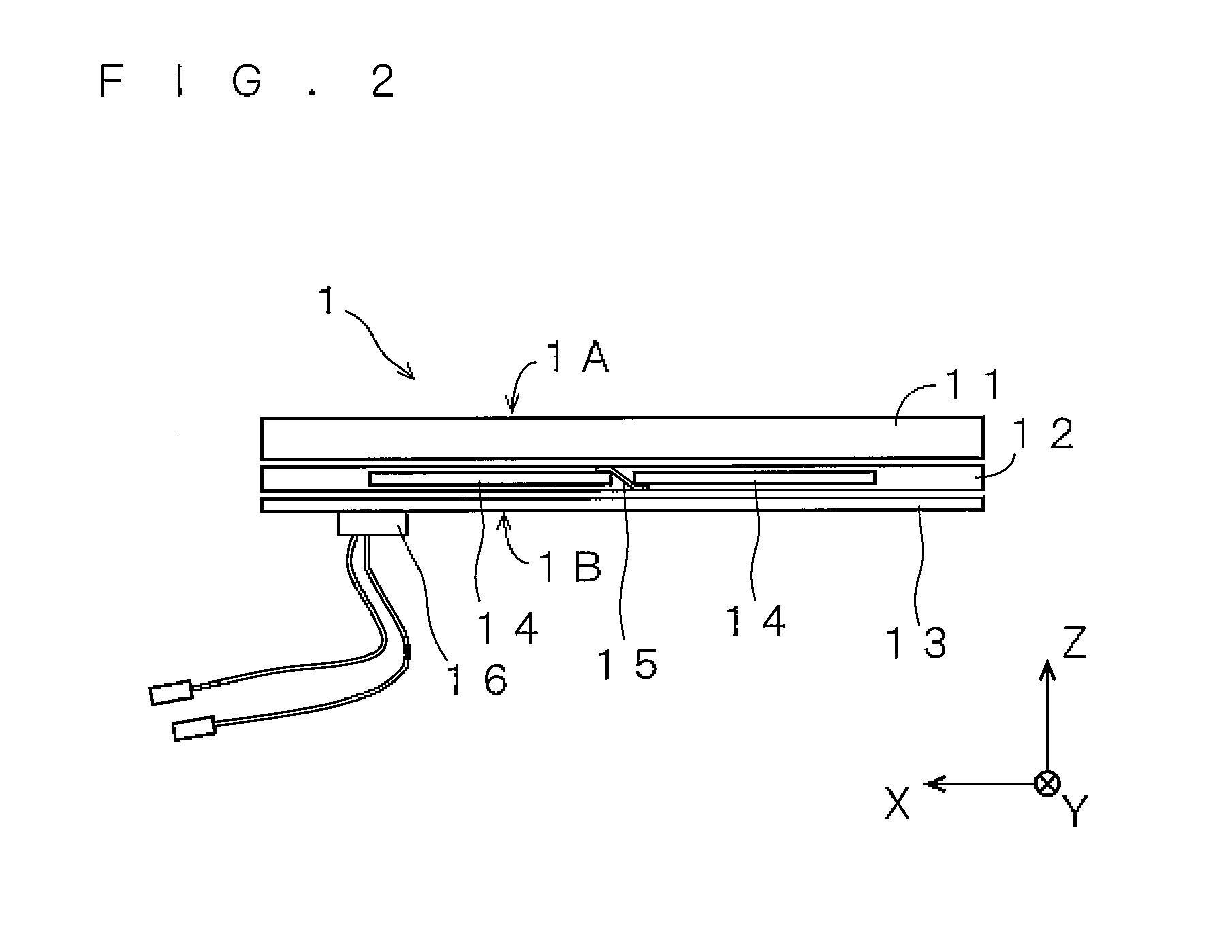
[0031]The solar cell module 1 can employ various structures such as a superstrate structure, a glass package structure and a substrate structure. Solar cell modules of the superstrate structure will be described as an example. The superstrate structure can be applied to monocrystalline silicon solar cells and polycrystalline silicon solar cells that are manufacture...

second embodiment

[0062]Next, a configuration of a photovoltaic power generating system 100a according to a second embodiment of the present invention will be described with reference to FIG. 7. In the description of this embodiment, elements having the same functions as those of the first embodiment are designated with the same symbols, and explanation thereof will be omitted. This also applies to other embodiments.

[0063]As shown in FIG. 7, the second embodiment includes a member 3a according to the first embodiment, and convex hollow supporting members 3c located above the member 3a.

[0064]Each of the supporting members 3c has a pyramidal shape whose cross section in the horizontal direction is gradually reduced toward the non-light-receiving surface 1B of the solar cell module 1. The supporting member 3c is made of elastic member (such as EPDM or natural rubber) so that it can be deformed when it abuts against the solar cell module 1.

[0065]According to this embodiment, if a positive pressure load ...

third embodiment

[0066]According to a third embodiment of the present invention, as shown in FIG. 8(a), supporting members 3d are provided on the side of the non-light-receiving surface 1B of the solar cell module 1. A distance between the supporting member 3d and the solar cell module 1 is set such that the distance becomes gradually smaller from a center portion toward end edges of the solar cell module 1. More specifically, a supporting surface 3dS of each of the supporting members 3d is curved in a concave manner with respect to the non-light-receiving surface 1B.

[0067]It is preferable that a distance between the supporting member 3d and the solar cell module 1 at each position is set such that the distance is smaller than a limit value of a bending amount of the solar cell module 1 at each position. It is preferable that the distance between the solar cell module 1 and the supporting member 3d is set such that the distance becomes the maximum at a center part of the solar cell module 1 when the...


PUM


Abstract

A photovoltaic power generating system of the present invention includes a solar cell module 1, an installation platform 2 for holding a pair of ends of the solar cell module 1, and at least one supporting member 3 disposed on a side of a non-light-receiving surface 1B of the solar cell module 1, wherein the supporting member 3 is disposed at such a distance from the non-light-receiving surface 1B of the solar cell module 1 that the supporting member 3 can abut against the non-light-receiving surface 1B by deformation of the solar cell module 1. A deforming amount of the solar cell module 1 is increased in accordance with an external force applied to the solar cell module 1.

Description

TECHNICAL FIELD[0001]The present invention relates to a photovoltaic power generating system.BACKGROUND ART[0002]As interest in environmental protection is increased in recent years, photovoltaic power generating systems having lower environment load have come to attention. To get the photovoltaic power generating systems widespread use, cost reduction is considered.[0003]For reducing the cost, it is proposed to provide a solar cell module of frameless (sashless) structure, or to increase an area of a power generator of the solar cell module. However, these proposals may cause deterioration of the strength. For example, since the solar cell module of frameless structure has low rigidity, the module easily bends, and the solar cell module is easily broken. If the area of the solar cell module is increased, a wind pressure and a snow accumulation load applied to one sheet of solar cell module are increased. Therefore, like the case of the solar cell module of frameless structure, a be...

Claims


Application Information

Patent Timeline
Patent Type & Authority Applications(United States)
IPC IPC(8): H01L31/048
CPCF24J2/5232F24J2/5233H01L31/048H02S20/23Y02E10/47Y02E10/50H02S20/00Y02B10/12F24S25/12F24S25/13H02S20/10H02S20/24Y02B10/10
Inventor KANBARA, TATSUJIHIRATA, HIROAKIFUKUI, HIDEAKISUMIDA, KENICHIRO
Owner KYOCERA CORP
Why Eureka
Try Eureka