Method for Online Cleaning of Air Preheaters

a technology of regenerative air heater and online cleaning, which is applied in the direction of cleaning heat-transfer devices, flush cleaning, combustion process, etc., can solve the problems of air and flue gas blocking, reducing heat transfer capacity, and more rapid deterioration of heat exchange elements in the rotor, so as to reduce the accumulation of deposits

Inactive Publication Date: 2011-01-13
BREEN ENERGY SOLUTIONS
View PDF16 Cites 15 Cited by
  • Summary
  • Abstract
  • Description
  • Claims
  • Application Information

AI Technical Summary

Benefits of technology

[0016]The present invention is directed toward a method of cleaning those sticky deposits, including ammonium bisulfate, sulfuric acid and other materials, from a rotary air preheater without shutting down the steam generating system. Further, this method can be used to mitigate the accumulation of deposits to the point of pluggage by changing the operating strategy of conventional soot blowers. This method is particularly effective when used wit...

Problems solved by technology

As these deposits build up, the flow paths for the air and flue gas become blocked and the heat transfer capacity is reduced.
This causes a more rapid deterioration of the heat exchange elements in the rotor usually toward the center and outside periphery of the rotor.
On an industrial scale, these requirements can only be achieved to a limited extent with acceptable capital outlay.
Consequently, it is inevitable that ammonia slippage may occur distributed unevenly across the cross-section of the reactor.
Because ammonium bisulfate is so sticky, it...

Method used


Image

  • Method for Online Cleaning of Air Preheaters
  • Method for Online Cleaning of Air Preheaters
  • Method for Online Cleaning of Air Preheaters

Examples


Embodiment Construction

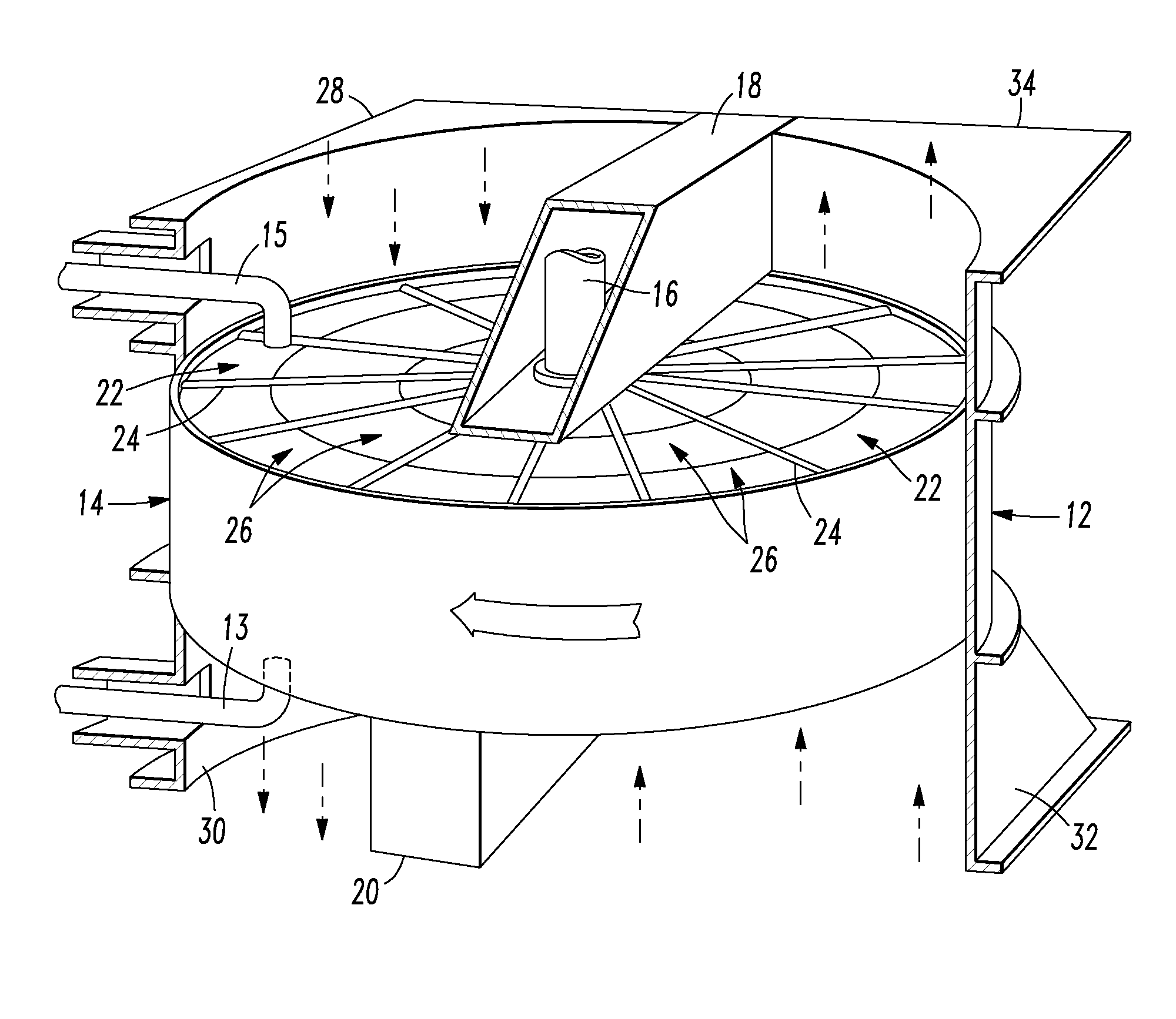
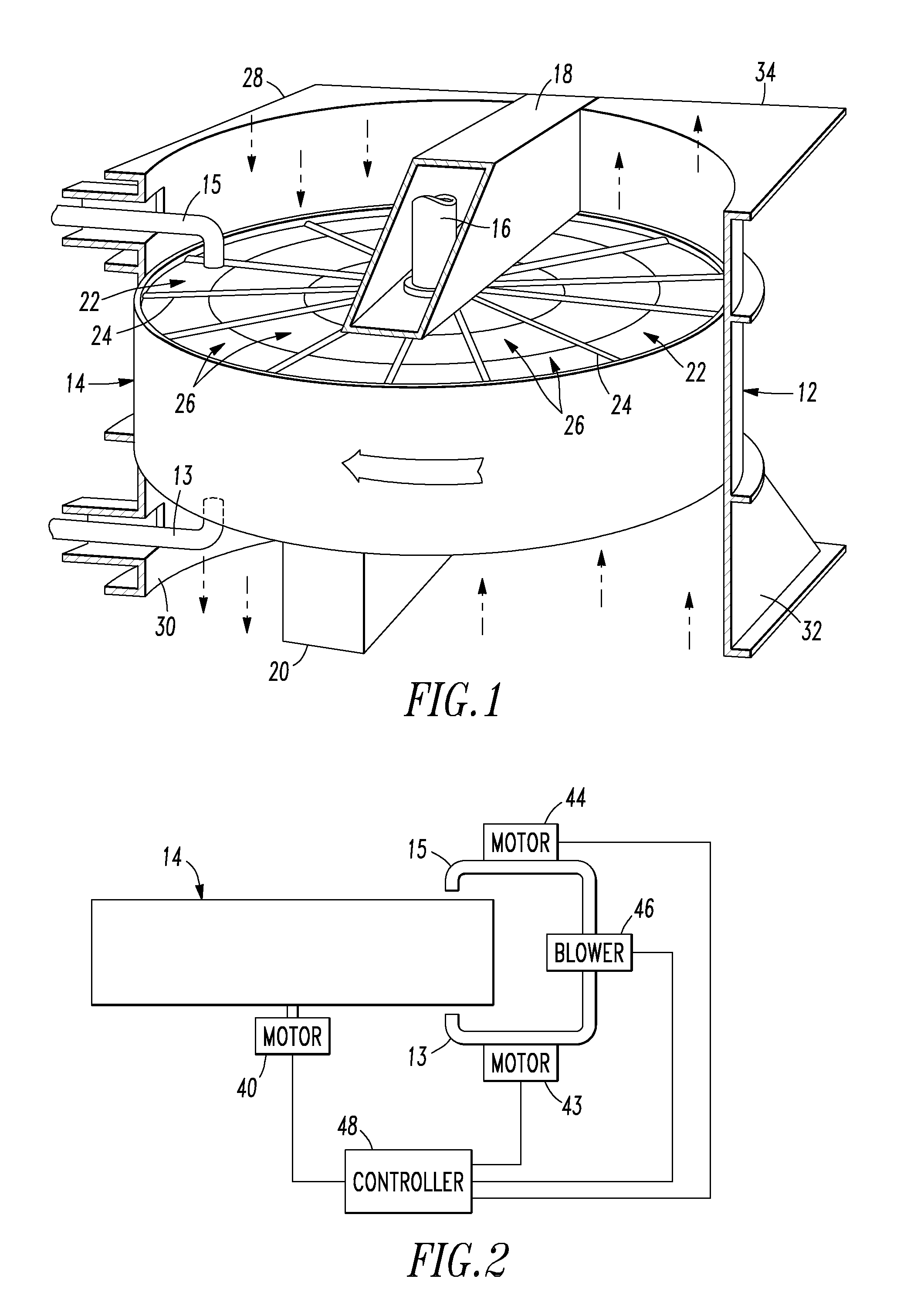
[0022]FIG. 1 is a perspective view of a typical air preheater in which flue gas travels in a vertical, up or down direction and is intended to illustrate one type of air preheater in which the present invention is used. The present invention may be applied to horizontal, vertical (cold end on the top) and vertical inverted (cold end on the bottom) air preheaters. FIG. 1 depicts a vertical air preheater with the cold end on the bottom. The air preheater comprises a rotor housing 12 in which is mounted the heat exchange rotor 14. The rotor is mounted for rotation on the shaft 16 which extends between the upper center section 18 and the lower center section 20. The rotor is divided into sectors or passageways 22 by the diaphragm plates 24 and heat exchange baskets 26 are stacked into these sectors 22. Located at the top and bottom of the air preheater and attached to the rotor housing 12 and to the top and bottom center sections 18 and 20, are the transition duct assemblies identified ...


PUM


Abstract

A method of cleaning air preheaters of the type having a rotor which passes through a stream of flue gas and a stream of intake combustion air is disclosed. A soot blower is operated in step-wise fashion to blow a soot blowing medium through passageways in the rotor. The passageways are arranged in concentric rings and move at a tangential velocity which depends on the speed of the rotor and the location of the passageway relative to the center of the rotor. In the present method the speed of the rotor is adjusted in accordance with the position of the soot blower so that every passageway moves over the soot blower at the same or substantially the same tangential velocity.

Description

FIELD OF THE INVENTION[0001]The present invention is directed toward a method for cleaning rotating regenerative air heaters used in coal-fired electricity generating plants.BACKGROUND[0002]Techniques for preheating of air have been known and used for many years in connection with boilers to improve combustion and boiler efficiency. One such preheating technique employs a Ljungstrom air preheater. This air preheater has two side-by-side ducts with flue gas flowing through one duct while an inflow of combustion air is passed through the other duct, the two gas flows being in opposite directions. A rotor is positioned to rotate through both ducts about an axis between the two ducts, transferring heat from the flue gas to the combustion air. Air preheaters, are normally operated at sufficiently high temperatures to inhibit condensation inside the heat exchanger of pollutants such as sulfuric acid vapor present in the flue gas. For example, in typical published temperature guide lines f...

Claims


Application Information

Patent Timeline
IPC IPC(8): F28D17/00
CPCF28D19/044F28G15/00F28G9/005F28G1/16
Inventor THOMAS, SCOTTLOCKERT, CHARLES A.
Owner BREEN ENERGY SOLUTIONS
Why Eureka
Try Eureka