
Power converter for electric rotating machine

a technology of power converter and electric rotating machine, which is applied in the direction of electronic commutators, motor/generator/converter stoppers, dynamo-electric converter control, etc., can solve the problems of increased loss of rectification in the inverter, unwanted unwanted shift in the off-time, so as to ensure the stability of the control of the electric rotating machine, avoid the backflow of current, and minimize the loss of rectification loss

Active Publication Date: 2011-01-13
DENSO CORP
View PDF2 Cites 26 Cited by
  • Summary
  • Abstract
  • Description
  • Claims
  • Application Information

AI Technical Summary

Benefits of technology

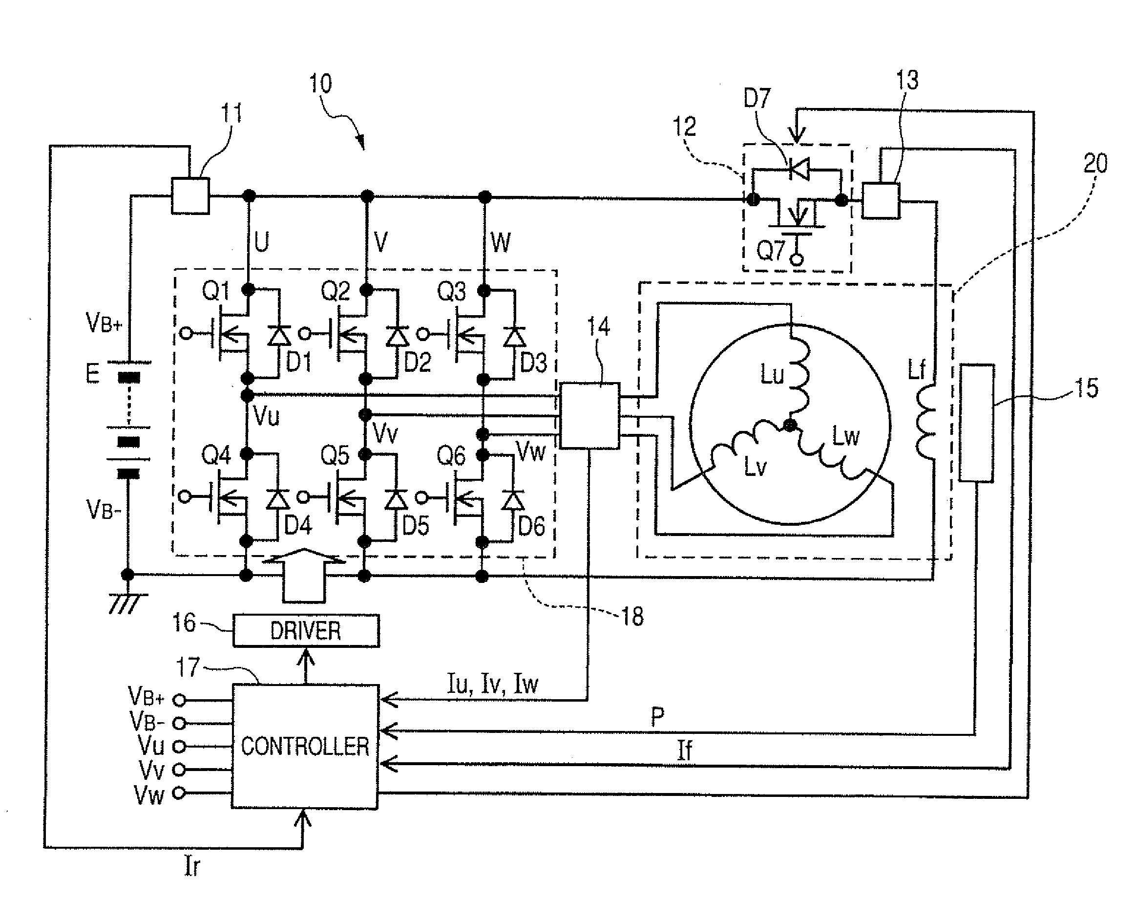
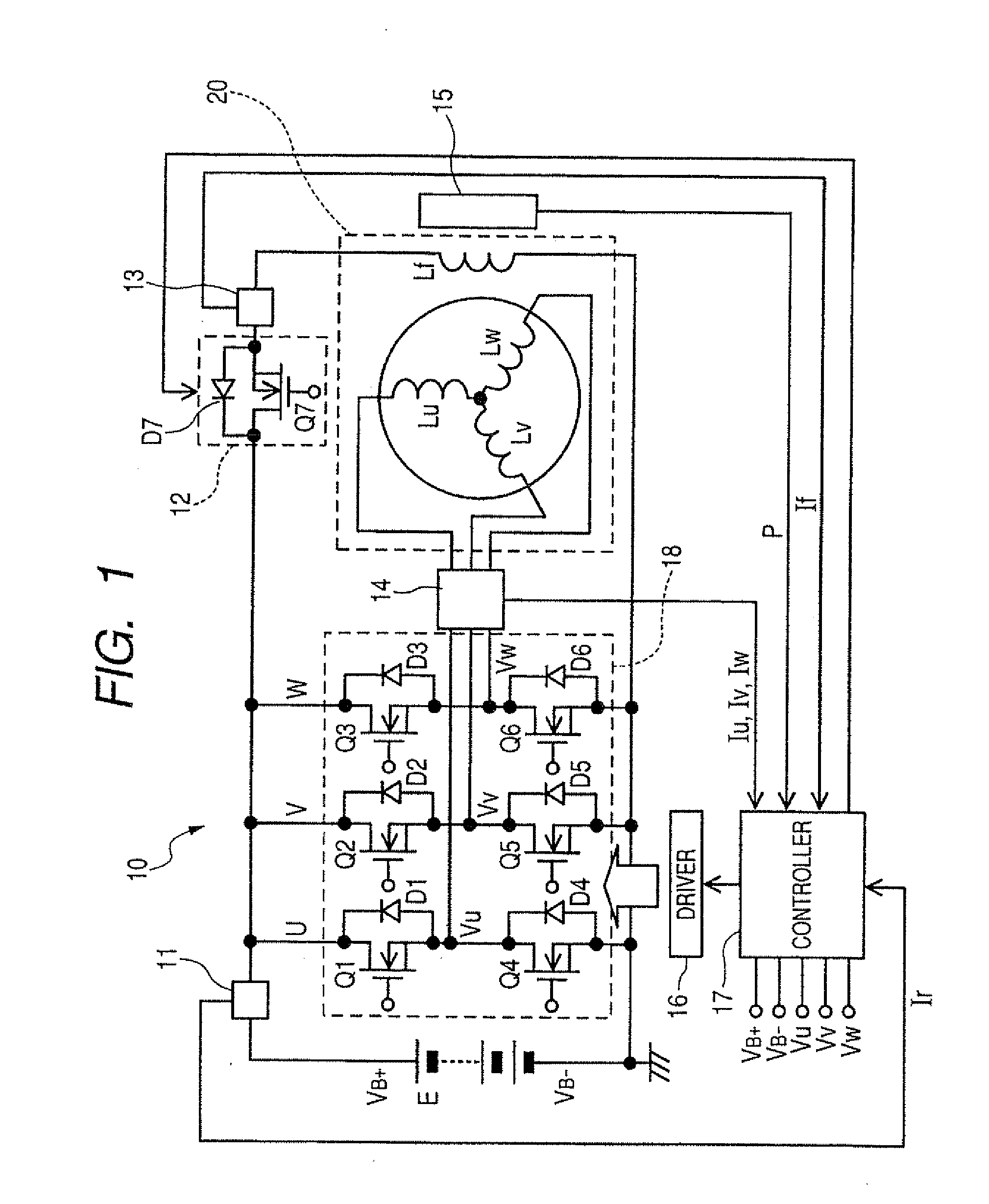
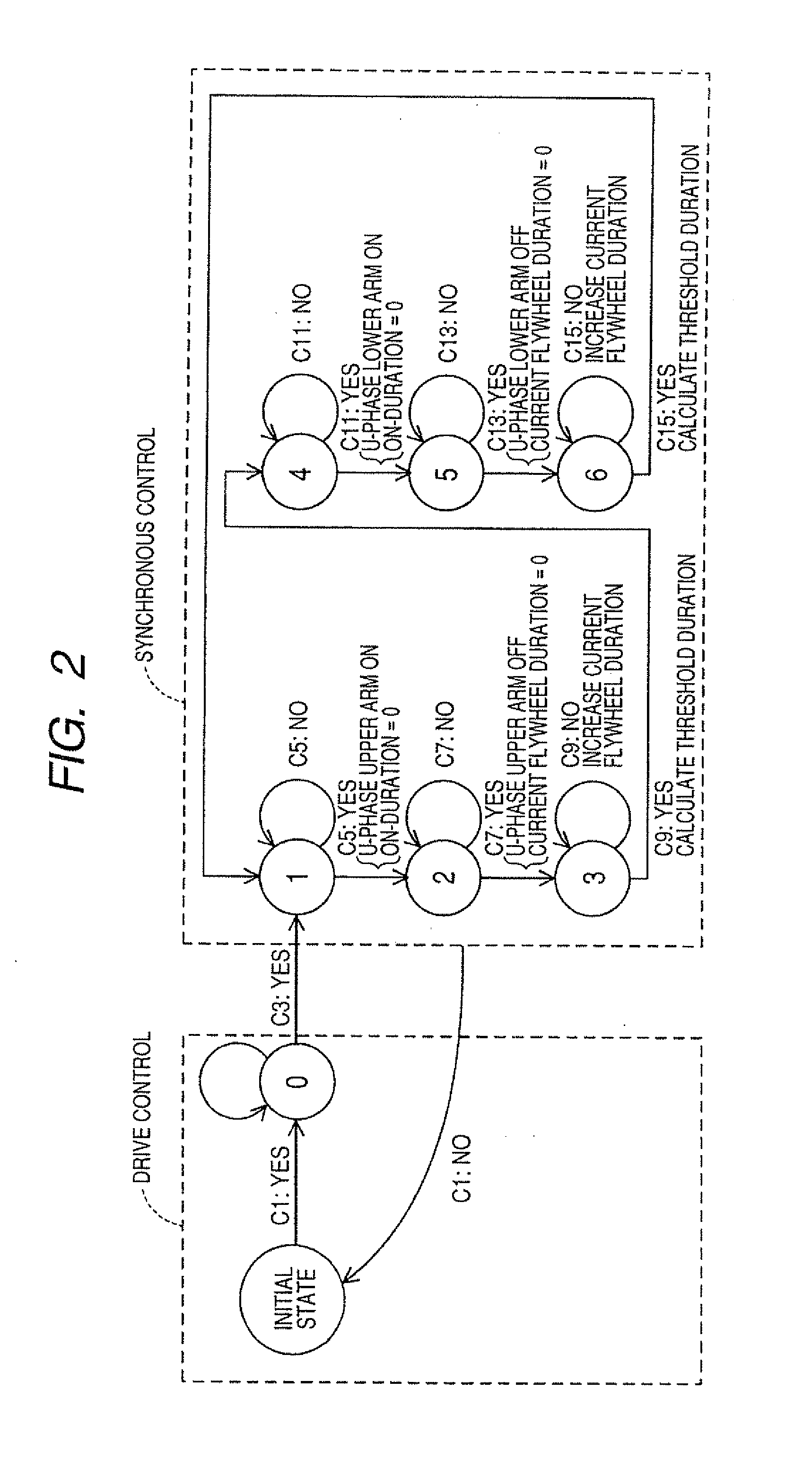
The invention is a power converter for an electric rotating machine that is designed to keep a current flywheel duration constant, even when the machine is subjected to sudden changes or uncertainties. This is achieved by controlling the off-operation of one of the arms of the converter, which allows for a set duration of current flywheeling. The power converter includes a switching circuit and a controller that controls the on-off operation of the upper and lower arms. The controller uses a position sensor to measure the angular position of the machine and ensure the current flywheel duration is set correctly. This results in a more reliable and accurate power converter that can operate in various situations.

Problems solved by technology

This control, however, has a difficulty in setting the on-duration of the MOS transistor accurately when the system is in a transient state or dealing with an unexpected change such as an aged deterioration in characteristic of the system or a change in ambient temperature, which results in unwanted shift in the off-time.
When the unexpected change has occurred, it also results in unwanted shift in the off-time.
The advancement of the off-time usually leads to an increased loss in rectification in the inverter.
Conversely, the delay of the off-time results in backflow of current from a power supply to windings of the motor generator.
In other words, the duration in which current freewheels to the MOS transistors working as rectifying devices is susceptible to change, thus resulting in deterioration of reliability in operation of the system.

Method used


Image

  • Power converter for electric rotating machine
  • Power converter for electric rotating machine
  • Power converter for electric rotating machine

Examples


second embodiment

[0138]FIG. 9 illustrates the power converter 10 designed to control the operation of an electric generator 31 for use in automotive vehicles. The generator 31 serves as an electric rotating machine and includes two stator windings 32 and 33, a field winding 34, two rectifier module groups 35 and 36, and a generation controller 37. Each of the rectifier module groups 35 and 36 works as a switching circuit for one of the stator windings 32 and 33. The generation controller 37 and the rectifier module groups 35 and 36 may alternatively be disposed outside the generator 31.

[0139]The stator winding 32 is a multi-phase winding made up of, for example, an X-phase winding, a Y-phase winding, and a Z-phase winding and wound around a stator core (not shown). Similarly, the stator winding 33 is a multi-phase winding made up of, for example, a U-phase winding, a V-phase winding, and a W-phase winding and wound around the stator core at an interval of 30° in electric angle away from the stator w...

first embodiment

[0147]As apparent from the above discussion, each of the rectifier modules 35X, 35Y, 35Z, 36U, 3617, and 36W is designed to perform functions of a portion of the switching circuit 18, the driver 16, and the controller 17, as illustrated in FIG. 1. In other words, the control circuit 54 works to monitor the phase voltage developed at a corresponding one of the X-, Y-, Z-, U-, V-, and W-phases windings and control the off-operation of each of the upper and lower arms (i.e., the MOS transistors 50 and 51) so as to secure a desired length of time in which the flywheel current Ir is permitted to flow in the same manner, as described in the The phase voltage may be derived in the control circuit 54 by measuring the drain voltage, as developed at either of the MOS transistors 50 and 51.


PUM


Abstract

A power converter for an electric rotating machine is provided which is designed to ensure a desired length of a current flywheel duration in which current is permitted to freewheel from the electric rotating machine even if the power converter is in a transient state or subjected to an unexpected change. The power converter is equipped with a controller and a switching circuit which is disposed between a power supply and windings of the electric rotating machine. The switching circuit has switches grouped into an upper and a lower arm. The controller works to control an off-operation of one of the switches of one of the upper and lower arm so as to produce a desired length of the current flywheel duration following turning off of the one of the switches, thereby minimizing a loss of rectification and avoiding the backflow of current from the power supply to the windings.

Description

CROSS REFERENCE TO RELATED DOCUMENT[0001]The present application claims the benefit of priority of Japanese Patent Application No. 2009-162448 filed on Jul. 9, 2009, the disclosure of which is incorporated herein by reference.BACKGROUND OF THE INVENTION[0002]1. Technical Field of the Invention[0003]The present invention relates generally to a power converter for an electric rotating machine which is equipped with a switching circuit and a controller, and more particular to such a power converter designed to ensure improved reliability in operation when the power converter is in a transient state or subjected to an unexpected change.[0004]2. Background Art[0005]Japanese Patent First Publication No. 2004-7964, assigned to the same assignee as that of this application, discloses an inverter for a three-phase motor generator and teaches a technique of setting an off-time of a MOS transistor for one of phases which is the time when the MOS transistor is to be turned off (i.e., after adva...

Claims


Application Information

Patent Timeline
Patent Type & Authority Applications(United States)
IPC IPC(8): H02P6/14H02P6/08H02M7/12H02P6/06H02P6/32
CPCH02P6/14H02M1/008
Inventor KONDO, TAIZOTAGO, MASAKAZUHORIHATA, HARUMI
Owner DENSO CORP
Learn More