Optical Helmet-Position Detection Device Having a Large Dynamic Range

a detection device and optical technology, applied in the direction of instruments, reflex reflectors, reradiation, etc., can solve the problem of increasing the cost of the detection system

Inactive Publication Date: 2011-01-13
THALES SA
View PDF4 Cites 6 Cited by
  • Summary
  • Abstract
  • Description
  • Claims
  • Application Information

AI Technical Summary

Benefits of technology

[0005]The object of the device according to the invention is to produce an optical position/orientation detection system that can be used in a wide range of illuminations, in daytime with illuminations of the order of 100 000 lux and at night with illuminations of the order of 0.01 lux. Under high illumination, the invention utilizes solar illumination instead of combating it, by employing passive

Problems solved by technology

However, the solar illumination levels are still high in the infrared and ultraviolet bands, and this type of sol

Method used


Image

  • Optical Helmet-Position Detection Device Having a Large Dynamic Range
  • Optical Helmet-Position Detection Device Having a Large Dynamic Range
  • Optical Helmet-Position Detection Device Having a Large Dynamic Range

Examples


first embodiment

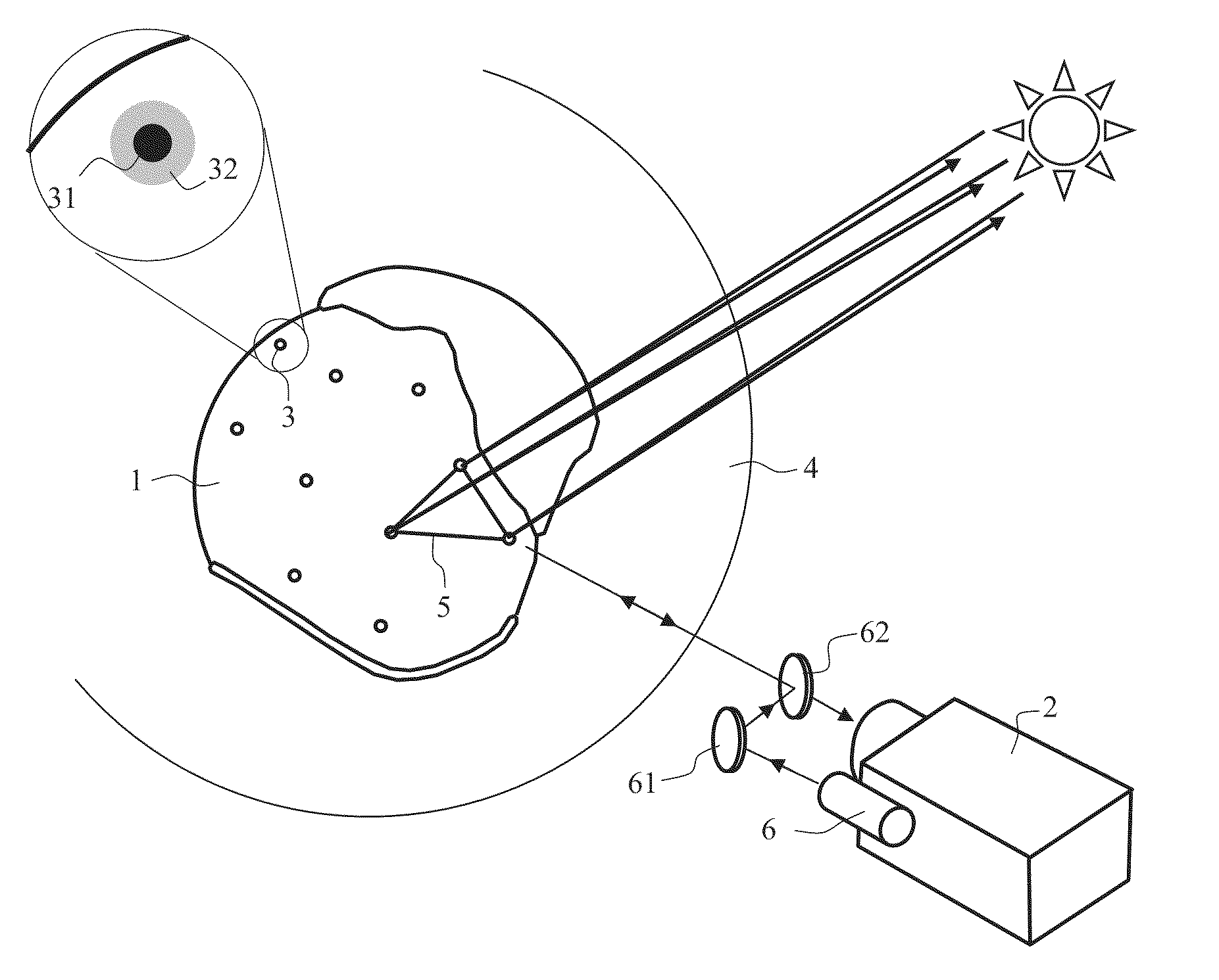
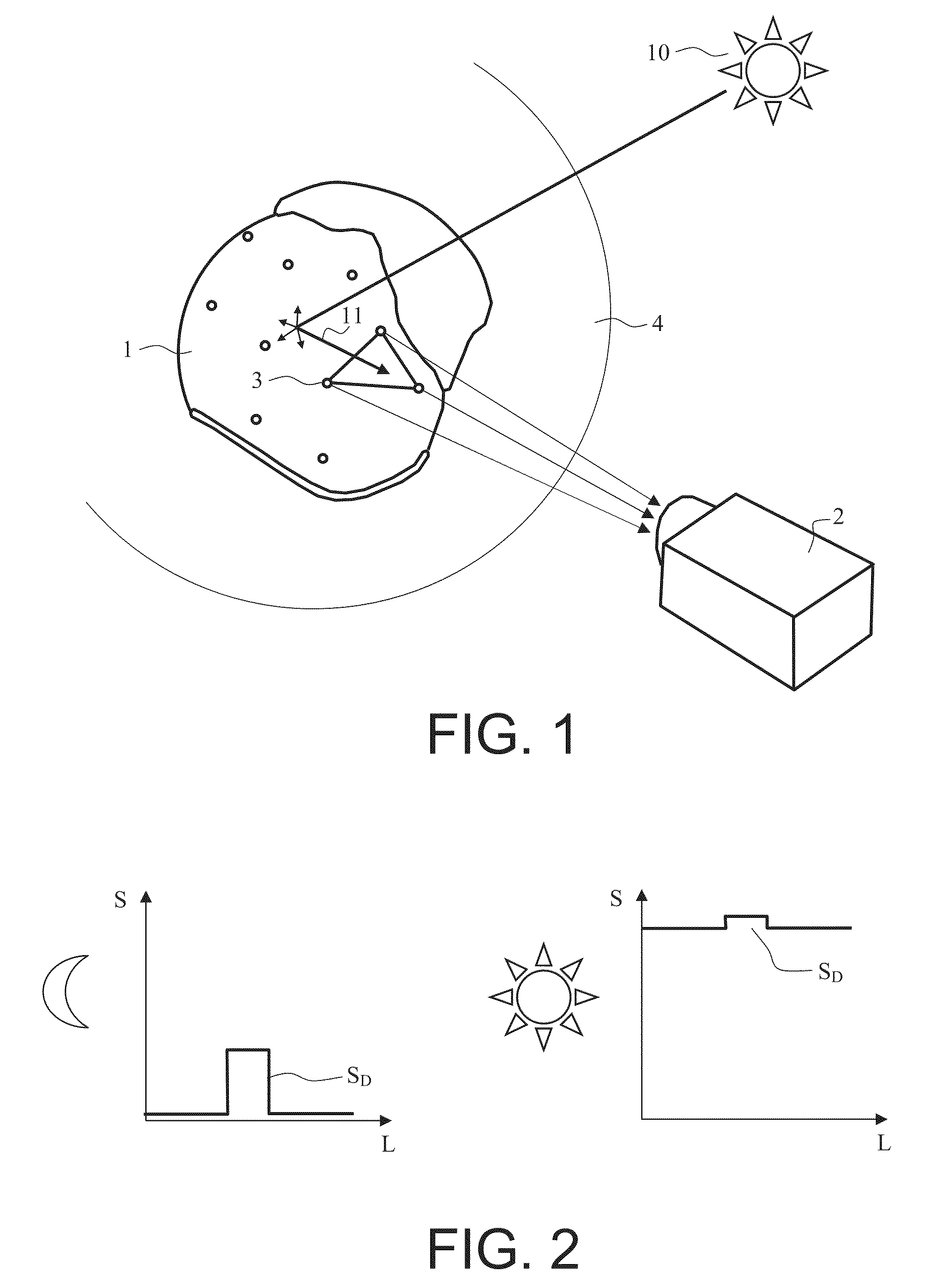
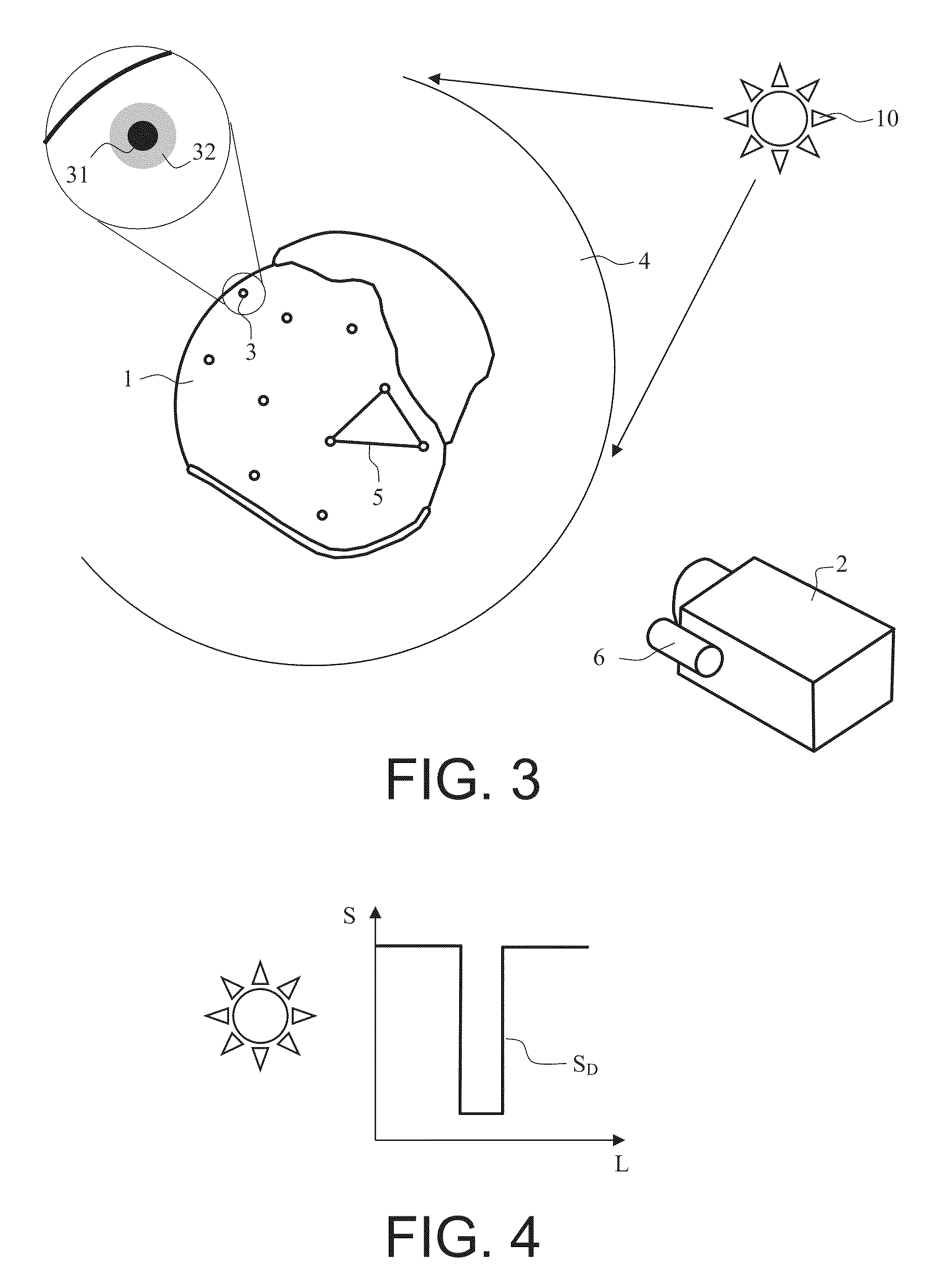
[0035]This second device essential differs from the first embodiment by the operation of the markers. In the present case, each marker 3 comprises a first optical element 31 of the “catadioptric” type, having a very high retroreflection coefficient and a very low scattering coefficient in the visible range. Thus, the solar radiation is necessarily reflected in the sun's direction, as may be seen in FIG. 8, and cannot reach the cameras. In the daytime, the operation is therefore identical to that of the previous device.

[0036]The term “catadioptric” refers to any optical reflector or retroreflector having the property reflecting a light beam in the same direction as its incident direction. To give an example, a “cube corner” reflector formed from three mutually orthogonal plane mirrors is a catadioptric reflector. Thus, a light beam emitted by the emitting part and illuminating the catadioptric reflector is re-emitted in the same direction towards the receiving part with an excellent ...

second embodiment

[0044]In the second embodiment shown in FIG. 8, the device includes optomechanical means of producing an image of the light source on the optical axis of the camera. In the case of FIG. 8, these means are simply a mirror 61 and a semireflecting plate 62 for mixing the two, source and camera, channels. In this case, the radiation from the source illuminating the catadioptric reflector is sent back to the camera. The catadioptric reflector appears bright on a dark background, as shown in FIG. 9. It no longer necessary for the marker 3 to include a second optical element 32. Advantageously, the helmet coating is of dark colour on the periphery of the catadioptric reflector.

[0045]To improve the detection, it is possible to make a number of modifications to the general arrangements described above. Thus, the light source, when it is present, will be turned off when the sunshine conditions are sufficient; it may be modulated temporally; it may be a scanning light source; it may be control...


PUM


Abstract

The general field of the invention is that of optical devices for detecting the position/orientation of a helmet. The device according to the invention comprises an optional stationary light source, a stationary camera associated with an image processing system, and a helmet. The helmet has a scattering coating and includes at least one set of markers, each marker comprising at least a first optical element having a very low reflection coefficient, a very low scattering coefficient and a very high absorption coefficient in the visible range and in that of the light source. In one embodiment, each marker may also include a first optical element having a very high retroreflection coefficient and a very low scattering coefficient in the visible range. The marker may also include a second optical element having a high scattering or phosphorescence coefficient in the emission range of the light source.

Description

CROSS-REFERENCE TO RELATED APPLICATIONS[0001]This application claims priority to foreign France patent application No. 0903422, filed on Jul. 10, 2009, the disclosure of which is hereby incorporated by reference in its entirety.FIELD OF THE INVENTION[0002]The field of the invention is that of optical devices for detecting the instantaneous position and orientation of the helmet worn by an aircraft pilot. In general, in the rest of the text the term “posture” refers to a particular position and a particular orientation of the helmet. For certain aeronautical applications, the helmets of pilots are provided with display devices for generating, in the pilot's field of view, information about the flight, the navigation or the reference system. These helmet visuals are generally coupled to systems for detecting the position and orientation of the helmet.BACKGROUND[0003]There are various systems for referencing the position of a helmet. In particular, systems based on the analysis of opti...

Claims


Application Information

Patent Timeline
IPC IPC(8): G06F3/033
CPCF41G3/225G01S5/163G01S17/46G02B5/003G06F3/012G02B27/0093G02B27/017G02B27/32G02B2027/0187G02B5/12
Inventor PERBET, JEAN-NOËLBARBIER, BRUNOPOTIN, LAURENT
Owner THALES SA
Why Eureka
Try Eureka