Device for optical distance measurement

Inactive Publication Date: 2011-01-13
ROBERT BOSCH GMBH
View PDF9 Cites 9 Cited by
  • Summary
  • Abstract
  • Description
  • Claims
  • Application Information

AI Technical Summary

Benefits of technology

In order to keep the positioning tolerance for the photodetector as small as possible and simultaneously achieve a deliberate damping of the signal component of the measurement signal when the distance to the object, respe

Problems solved by technology

On the other hand, biaxial distance-measuring devices have among other things the disadvantage that detection problems may arise due to parallax when close-range distance measurements are performed.
Althoug

Method used


Image

  • Device for optical distance measurement
  • Device for optical distance measurement
  • Device for optical distance measurement

Examples


Embodiment Construction

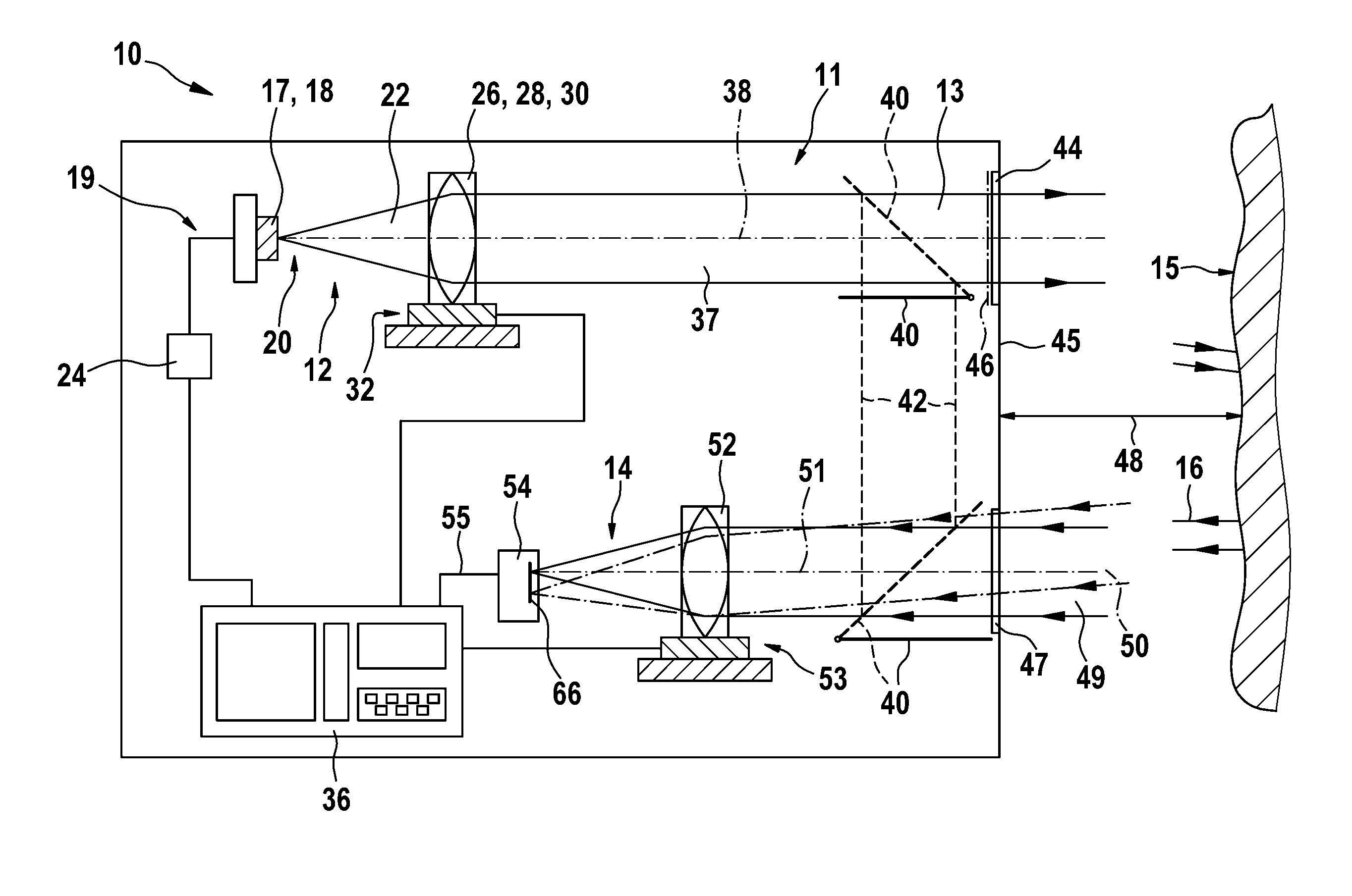
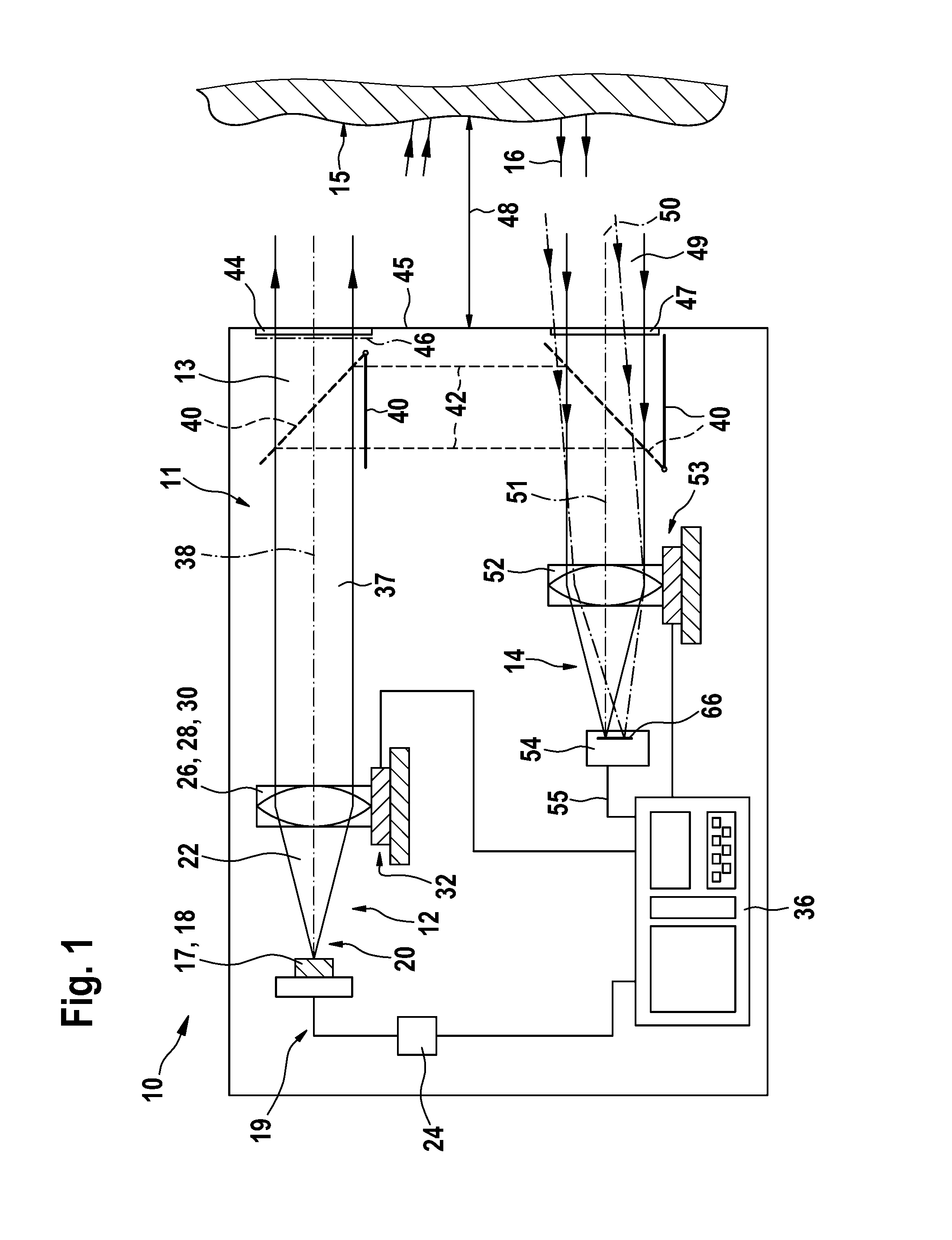
An inventive device for optically measuring distance is depicted in a schematized manner in FIG. 1 including the most important components, whose function will be described.

The inventive device 10 includes a housing 11, in which a transmission unit 12 for generating a measurement signal 13 and a receiving unit 14 for detecting the measurement signal 16 returning from a target object 15 are disposed.

The transmission unit 12 includes a light source 17, which is realized as a semiconductor laser diode 18 in the exemplary embodiment shown in FIG. 1. It is also possible to use other light sources in the inventive device. The laser diode 18 emits a laser beam 20 in the form of a light bundle 22 that is visible to the human eye. Green, red or blue light are advantageously used in this instance.

The laser diode 18 is operated via a control unit 24, which modulates the electrical input signal 19 of the diode using appropriate electronics. Via a modulation of the diode current carried out in s...


PUM


Abstract

The invention relates to a device for optical distance measurement, particularly to a handheld device, comprising a transmission unit (12) with a light source (17, 18) for emitting optical measurement radiation (13, 20, 22) onto a target object (15), and comprising a receiving unit (14) arranged at a distance from the optical axis (38) of the transmission unit (12) and equipped with at least one optical detector (54) for receiving optical radiation (16, 49, 50) reflected from the target object (15). According to the invention, the detector (54) of the receiving unit (14) comprises a detection surface (66), the optical surface of which has varying optical sensitivity.

Description

TECHNICAL FIELDDISCLOSURE OF THE INVENTIONThe invention relates to a device for optical distance measurement according to the preamble of the independent claim.Optical distance-measuring devices as such have been known for some time and are now sold commercially in large numbers. These devices emit a modulated, respectively pulsed, light beam, which is directed toward the surface of a desired target object, whose distance from the device is to be ascertained. A portion of the returning light, which has been reflected or scattered by the target object, is detected by the device and used to ascertain the distance in question.The application range of such distance-measuring devices generally comprises distances in the range of a few centimeters to several hundred meters. Depending upon the paths to be measured and the reflectance of the target object, different requirements result for the light source, the quality of the measurement beam as well as for the detector.The optical distance...

Claims


Application Information

Patent Timeline
IPC IPC(8): G01B11/14G01S17/32
CPCG01S7/4816G01S17/32G01S17/08
Inventor WOLF, PETERRICHARD, MATTHIEUBRAUN, ANDREASSTIERLE, JOERGHAASE, BJOERNRENZ, KAI
Owner ROBERT BOSCH GMBH
Why Eureka
Try Eureka