
Retinal implant with rectified ac powered photodiode

a photodiode and retinal implant technology, applied in the field of microelectronic elements, can solve the problems of reduced performance, complete failure of the device, and potentially corroding environment of the microelectronic, and achieve the effects of reducing electrochemical corrosion, prolonging the life of the medical implant device, and ensuring stability

Inactive Publication Date: 2011-01-13
PIXIUM VISION SA
View PDF3 Cites 13 Cited by
  • Summary
  • Abstract
  • Description
  • Claims
  • Application Information

AI Technical Summary

Benefits of technology

[0006]It is therefore an object of the present invention to provide a medical implant device in which the sensitive microelectronic components of the device are adequately protected from the aqueous environment of the human or animal body, without all of the drawbacks or limitations noted above.

Problems solved by technology

In particular, the moisture or fluids of the human or animal body to which such medical implant devices are almost invariably exposed are typically electrolytic conductors and create a potentially corrosive environment for the microelectronic components, especially when those components are supplied with a direct current (DC) voltage via a battery power source or a converted alternating current (AC) power supply.
When the microelectronic components are exposed to corrosive influences, the efficacy of the medical implant device can be compromised leading to reduced performance or even to a complete failure of the device.
For example, when an optical receiver element is used in an environment where it is exposed to aqueous solutions or other liquids, proper functioning of the receiver element may be impaired by electrochemical corrosion.
Such a coating layer, however, not only complicates the manufacturing process, but also has the problem that the microelectronic components still need to maintain an electrical contact with external components.
This often requires that a physical connection be provided through the protective enclosure or coating layer and, thus, a breach in the protective enclosure or layer is created.
Additionally, while sealing some components or the entire implant device with, for example, a polymer coating layer can provide effective protection from a corrosive environment, it can also involve a conflict between the requirements of impermeability to moisture on the one hand, and flexibility of the implant device on the other, particularly in the field of retinal implants.

Method used


Image

  • Retinal implant with rectified ac powered photodiode
  • Retinal implant with rectified ac powered photodiode
  • Retinal implant with rectified ac powered photodiode

Examples


Embodiment Construction

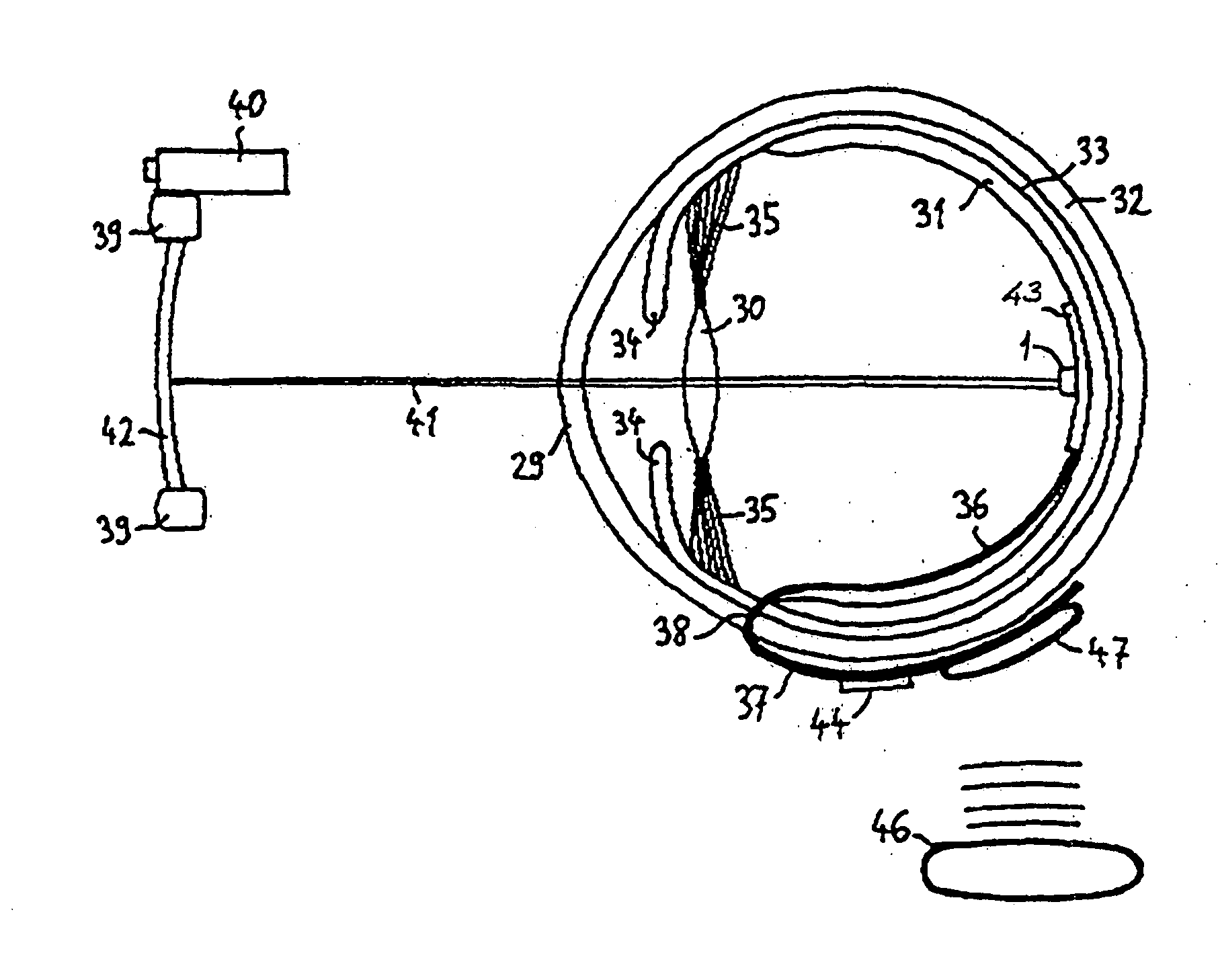
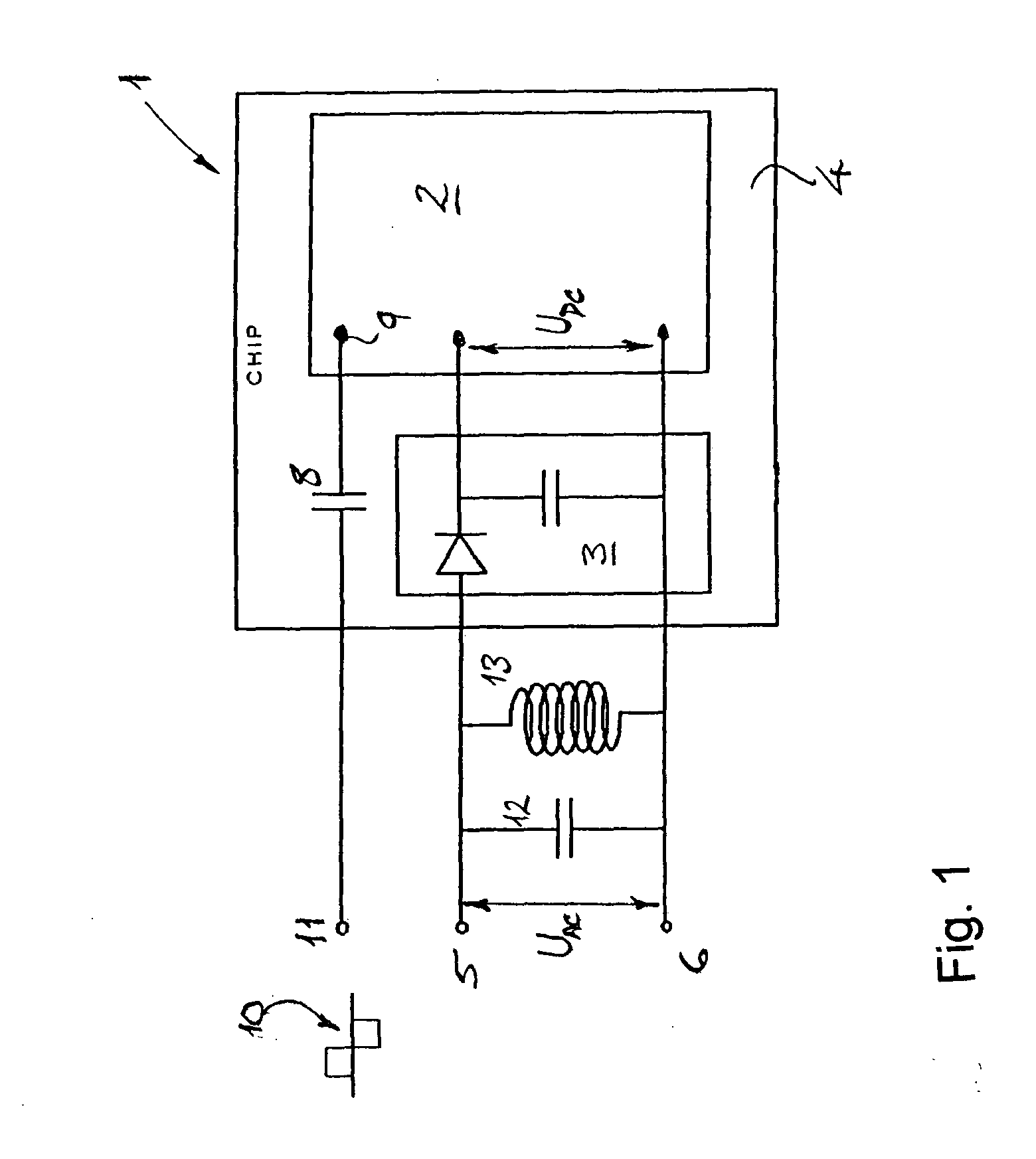
[0027]Referring firstly to FIG. 1 of the drawings, a microelectronics element in the form of a microchip 1 illustrating an example of the invention is shown. The microchip 1 is designed to be implanted in the human or animal body in a medical implant device and comprises application specific microelectronics in a functional unit 2 for performing a function in the medical implant device, and rectifier means 3 adapted for converting an AC supply voltage into a DC voltage. In this example, the rectifier means 3 comprises at least one diode and may include one or more filter capacitor or buffer capacitor for generating a smoothed DC voltage. It will be appreciated, however, that the rectifier means 3 may take a variety of different forms (e.g. a diode bridge-type rectifier, a voltage-adjusting rectifier, etc.) and may comprise an active rectifier circuit or a passive rectifier circuit.

[0028]Both the functional unit 2 and the rectifier means 3 are integrated on a common semiconductor sub...


PUM


Abstract

The present invention relates to a microelectronics element, such as an optical receiver element, for a medical implant device to be implanted in the human or animal body, particularly for a retinal implant device. The microelectronics element comprises a functional unit including application specific microelectronics, such as a photodiode, for performing a function in the medical implant device, and rectifier means adapted for converting an AC supply voltage into a DC voltage. The DC voltage provided by the rectifier means, or an operating voltage derived from the DC voltage, is configured to be supplied to the functional unit. Further, the functional unit and the rectifier means are integrated on a common semiconductor substrate and configured such that the rectifier means isolates the microelectronics element from application of an external DC supply voltage. The invention also relates to a medical implant device, such as a retinal implant, which incorporates such a microelectronics element.

Description

CROSS-REFERENCE TO RELATED APPLICATIONS[0001]This application is a U.S. Nationalization of PCT International Application No. PCT / EP2009 / 000176 filed 14 Jan. 2009, entitled “RETINAL IMPLANT WITH RECTIFIED AC POWERED PHOTODIODE,” which claims the benefit of PCT International Application No. PCT / EP2008 / 000231 filed 14 Jan. 2008, entitled “OPTICAL RECEIVER ELEMENT” the entireties of which are incorporated herein by reference.TECHNICAL FIELD[0002]The present invention relates to a medical implant device, and more particularly to a microelectronics element, such as a microchip, to be incorporated in the medical implant device.[0003]In a particularly preferred application of the present invention, the medical implant device comprises a retinal implant and the microelectronics element may be in the form of an optical receiver element for the retinal implant. It will be appreciated, however, that the present invention is not limited to this particular application, but may be employed in vari...

Claims


Application Information

Patent Timeline
IPC IPC(8): A61F2/16
CPCA61N1/025A61N1/36046A61N1/0543A61N1/3787
Inventor TIEDTKE, HANS-JURGEN
Owner PIXIUM VISION SA
Learn More