
Biomedical implantable material and methods of producing the same

a biomedical implantable material and implantable material technology, applied in the field of biomedical implantable material, can solve the problems of long recovery period, high cost of implant surgery, patient pain,

Active Publication Date: 2011-01-13
UNIV OF MARYLAND
View PDF23 Cites 31 Cited by
  • Summary
  • Abstract
  • Description
  • Claims
  • Application Information

AI Technical Summary

Benefits of technology

[0010]The present invention provides a biomedical implantable material comprising a plurality of pores, wherein two or more of the pores are interconnected below the surface of the material. The present invention also provides biomedical implant devices comprising the biomedical implantable material.
[0011]The present invention further provides processes for producing an improved biomedical implantable material, comprising subjecting an implantable material to a pore-forming treatment, and optionally further subjecting the implantable material to a surface-modifying treatment.

Problems solved by technology

Implant surgeries are often very costly and painful, and result in a long recovery period.
Revision surgeries are often necessary when the existing implant, after time, fails to perform its function properly and / or causes pain to the patient.
Patients with failed implants such as these are often elderly and in a weakened physical state, which can augment the risks associated with major surgery.
One of the main causes of low implant longevity is a poor implant-to-bone bonding, or interfacial strength.
However, such methods, which involve the creation of pores in an uncontrolled fashion, have failed to adequately meet the need in the art to provide biomedical implants made of implantable material which demonstrate improved longevity and durability and can improve the quality of life and reduce medical costs.

Method used


Image

  • Biomedical implantable material and methods of producing the same
  • Biomedical implantable material and methods of producing the same
  • Biomedical implantable material and methods of producing the same

Examples


example 1

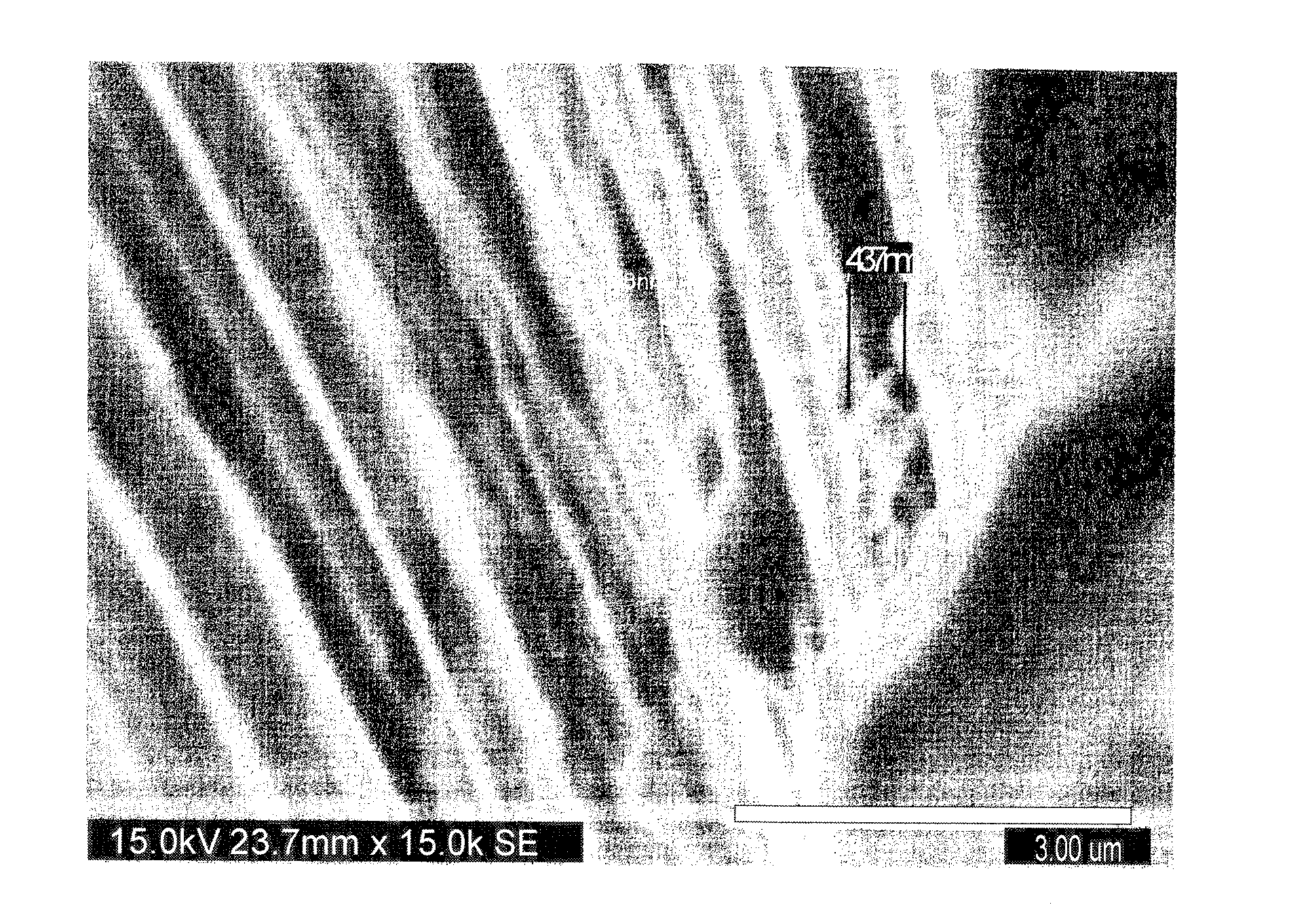
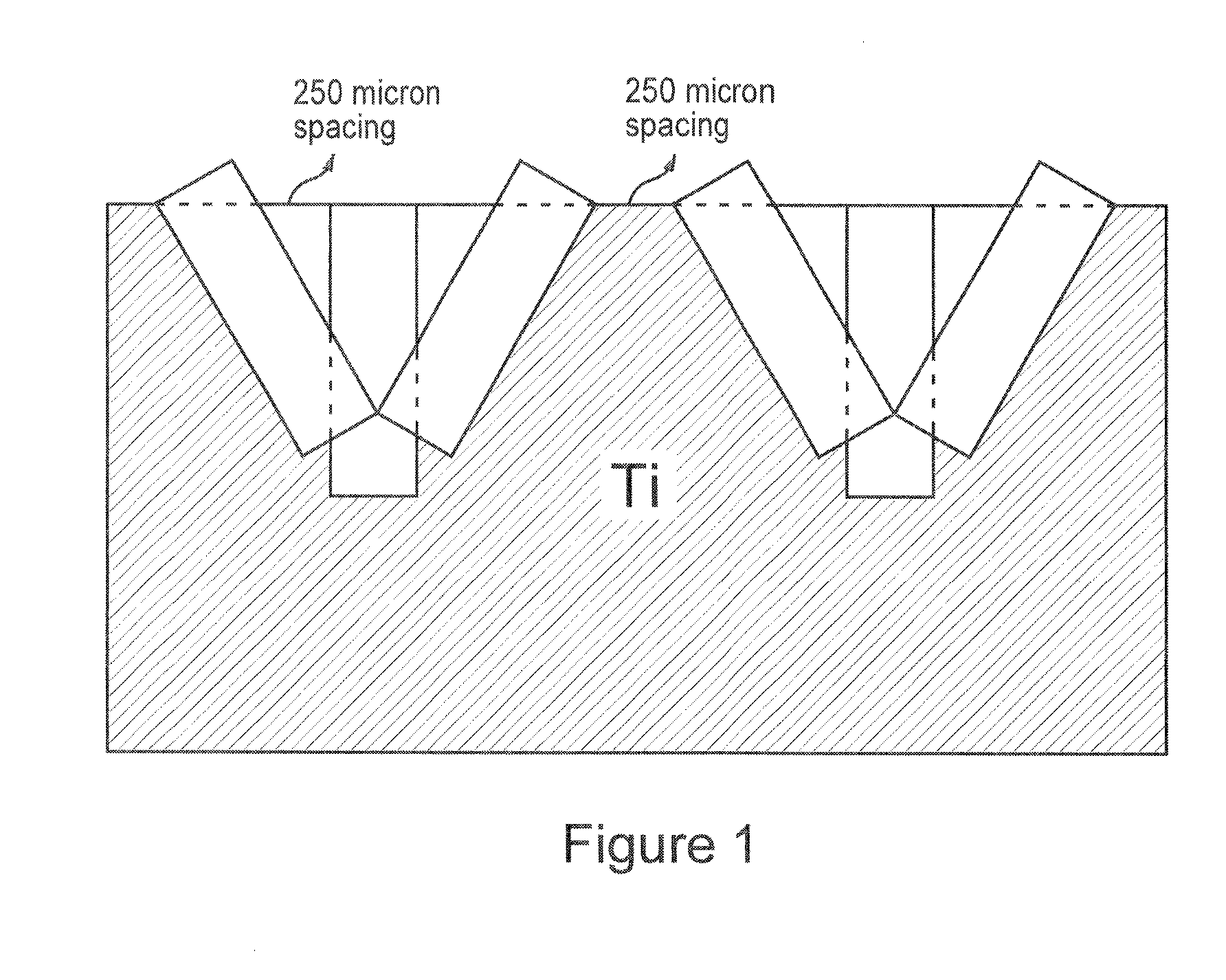
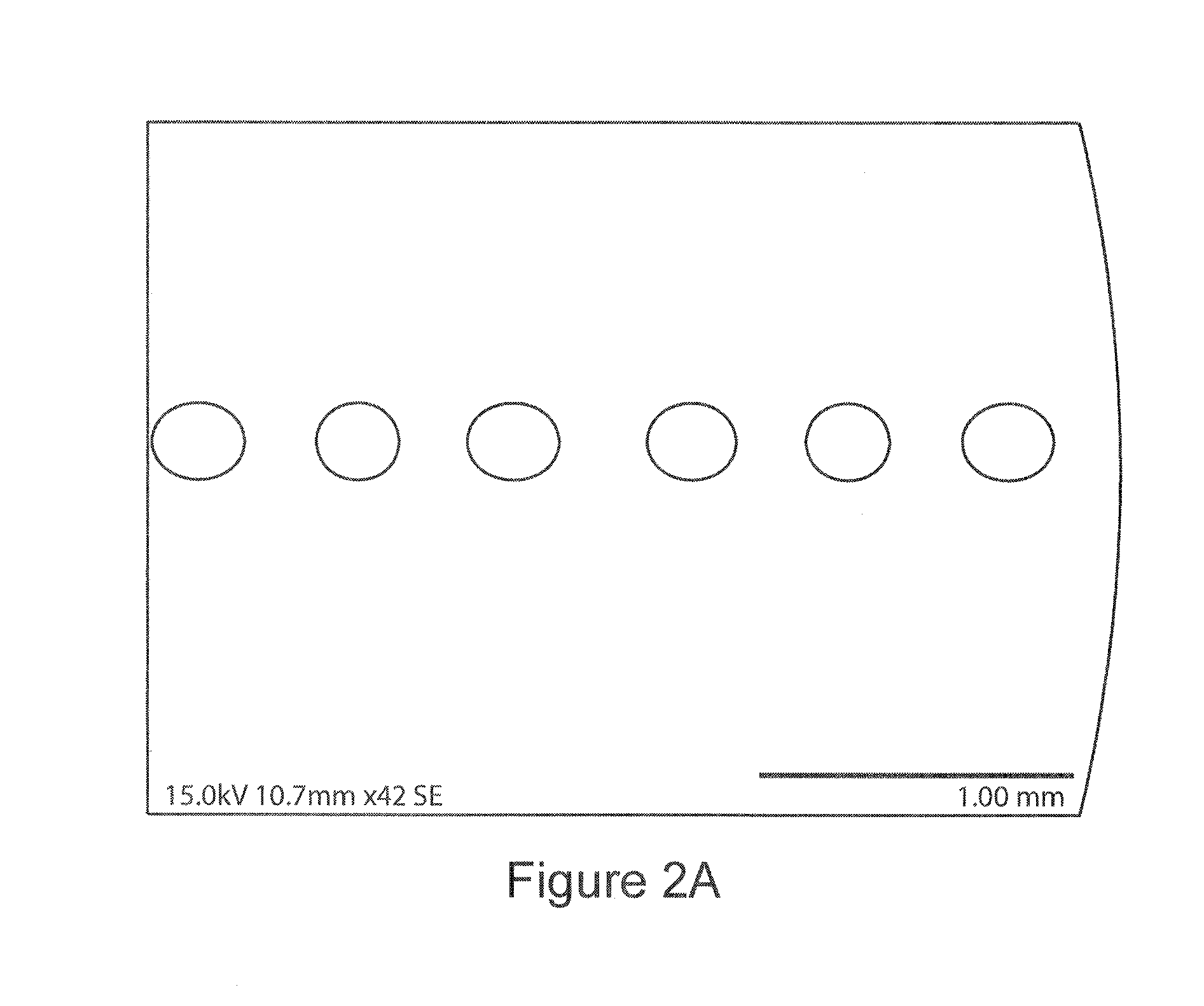
[0039]A 2 mm thick×12.7 mm diameter CP Grade 4 disk comprising titanium was subjected to electro-discharging machining to create six perpendicular and angled pores. FIG. 1 shows a schematic diagram showing the expected pore or hole configuration geometry, as made by the electro-discharging machining (EDM) technique. FIG. 1 shows that the pore diameter is 250 microns, and the pores are spaced 250 microns apart. Two angled pores, which are at a 30° angle with respect to the surface, are interconnected to a perpendicular pore. The pores have a depth of about 1 mm. The nano-roughness of the surface of the pores after electro-discharging machining treatment is about 225 nm. After treatment with thermal oxidation at 250° C. under forced air, a layer of titanium oxide is formed on the surface of the pores, which have a nano-roughness of about 400 nm.

[0040]The pore morphology, including nano-roughness, was characterized by scanning electron microscopy (SEM) and x-ray diffraction (XRD). FIGS...


PUM

PropertyMeasurementUnit
diameteraaaaaaaaaa
depthaaaaaaaaaa
angleaaaaaaaaaa

Abstract

The present invention relates to improved biomedical implantable material comprising a plurality of pores, of which one or more of the pores are interconnected below the surface of the material. The improved biomedical implantable material may be used in biomedical implant devices such as orthopedic implants, spinal implants, neurocranial implants, maxillofacial implants, and joint replacement implants. The present invention also relates to a method of preparing an improved biomedical implantable material, comprising subjecting an implantable material to a pore-forming treatment and optionally further subjecting the material to a surface-modifying treatment. The biomedical implantable material may be used in other applications, which as applications where two surfaces are contacted and bonding between the surfaces is required.

Description

[0001]This application is Non-Provisional application which claims priority to provisional application No. 61 / 240,024, filed Sep. 4, 2009, and provisional application No. 61 / 166,463, filed Apr. 3, 2009, the entire specification claims and drawings of which are incorporated herewith by reference.[0002]This invention was made with government support under contract number CMMI0733522 awarded by NSF. The government has certain rights in this invention.FIELD OF THE INVENTION[0003]The present invention provides a biomedical implantable material for use in implants, such as orthopedic implants, and methods of making the same.BACKGROUND OF THE INVENTION[0004]Biomedical implants, such as hip replacement joints and orthopedic implants, have been beneficial to patients with degenerative disease and patients suffering from disabling injuries. Implant surgeries are often very costly and painful, and result in a long recovery period. Many patients with implants are often required to undergo at le...

Claims


Application Information

Patent Timeline
Patent Type & Authority Applications(United States)
IPC IPC(8): A61F2/44A61F2/32A61F2/38A61F2/42A61F2/02A61F2/30B32B5/18B32B3/26B28B1/48B05D5/00B28B1/00B23K26/00
CPCA61F2/30771Y10T428/26A61F2/44A61F2002/3084A61F2002/3092A61F2002/30978A61F2310/00011A61F2310/00023B22F2998/10B23K26/0084B23K2203/14C22C1/08A61F2/32B22F3/10B22F2003/248B22F2003/241A61L27/06A61L27/56B23K26/355B23K2103/14Y10T428/249921
Inventor ANKEM, SREERAMAMURTHY
Owner UNIV OF MARYLAND
Learn More