Methods Of Controlling An Internal Combustion Engine Including Multiple Fuels And Multiple Injectors

a technology of injectors and fuels, applied in the direction of electrical control, process and machine control, instruments, etc., can solve the problems of increased knock, inefficient fuel economy, system is inherently difficult to control accurately and consistently on a cycle-to-cycle basis, etc., to improve fuel economy and reduce knock

Inactive Publication Date: 2011-01-13
VISTEON GLOBAL TECH INC
View PDF24 Cites 32 Cited by
  • Summary
  • Abstract
  • Description
  • Claims
  • Application Information

AI Technical Summary

Benefits of technology

[0009]The present invention is directed towards a method for controlling both the start of combustion and peak burn rate of an internal combustion engine system. The method can be used to control an engine using multiple fuels and including multiple injectors. The method includes controlling a fuel ratio, an injection ratio, and a residual gas recirculation ratio. The ratios are used to control a start of combustion and a peak burn rate. The method provides for accurate and consistent control of the start of combustion and peak burn rate of an HCCI engine system on a cycle-to-cycle basis. The controlled start of combustion and peak burn rate can lead to improved fuel economy and reduced knock.
[0010]The start of combustion and peak burn rate can be advanced or retarded by adjusting or tuning the three control ratios of the system, namely the fuel ratio, injection ratio, and residual as recirculation ratio. In other words, the control algorithms for both the start of combustion and peak burn rate include the fuel ratio, injection ratio, and residual gas recirculation ratio. A control module including a feed forward controller and a multi-input and multi-output controller can be used to tune the three control ratios and monitor the conditions and parameters of the engine. Also, the same operating parameters, specifically in-cylinder pressure or ionization signal, can be used to detect both the start of combustion and peak burn rate. Thus, the start of combustion and peak burn rate can be controlled consistently and accurately on a cycle-to-cycle basis so that the engine achieves optimal performance. Another advantage of the method is that it provides for a cost-effective and energy efficient engine system. A single control module can measure the relevant operating parameters of the system. No additional engine parts or significant amounts of energy, which could reduce the engine power and fuel economy, are required. Also, the control algorithm provides quick detection of the system parameters and quick adjustments of the ratios on a cycle-to-cycle basis.

Problems solved by technology

However, there is no direct or well-defined initiator of combustion in HCCI engine systems, so the system is inherently challenging to control accurately and consistently on a cycle-to-cycle basis.
Without accurate and consistent control, inefficient fuel economy and increased knock may occur.
An HCCI system is especially difficult to control in engines using multiple fuels and including multiple fuel injectors, due to the increased number of variables.
However, this approach requires a significant amount of energy to achieve fast responses, is expensive to implement and manufacture, and the reliability of such a system over the life cycle of a vehicle and in different environments is unknown.
However, this method is slow and cannot be adjusted on a cycle-to-cycle basis, which may result in inaccurate control.
However, FTM has limitations associated with actuator energy and is expensive to implement.
However, this method does not allow the residual exhaust gas recirculation rate to remain at a predetermined desired level on a cycle-to-cycle basis, which may lead to inconsistencies in the start of combustion.
The inability to accurately and consistently control the start of combustion in an HCCI engine system hinders the widespread commercialization of HCCI engine systems in internal combustion engines.

Method used


Image

  • Methods Of Controlling An Internal Combustion Engine Including Multiple Fuels And Multiple Injectors
  • Methods Of Controlling An Internal Combustion Engine Including Multiple Fuels And Multiple Injectors
  • Methods Of Controlling An Internal Combustion Engine Including Multiple Fuels And Multiple Injectors

Examples


Embodiment Construction

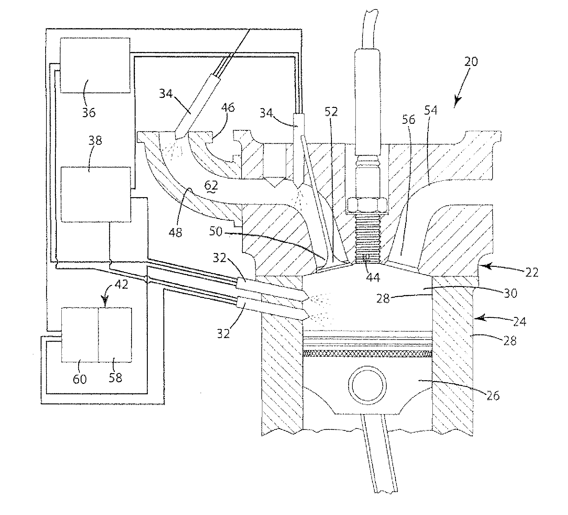
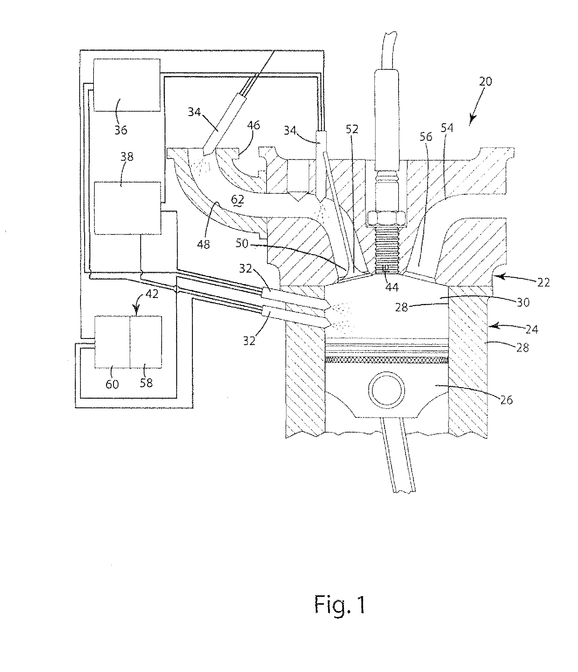
[0018]Referring to the Figures, wherein like numerals indicate corresponding parts throughout the several views, an exemplar internal combustion engine 20 incorporating the present invention is generally shown in FIG. 1. The engine 20 shown in FIG. 1 and described below is given by way of illustration only and does not limit the scope of the present invention.

[0019]The present invention is well suited to work with internal combustion engines 20 that can operate by a spark ignition engine system, a homogeneous charge compression ignition (HCCI) or spark-assisted HCCI engine system. The engine 20 generally includes an engine block 22 including a cylinder 24 formed in the engine block 22 and a piston 26 which moves up and down in the cylinder 24. The piston 26 and inside wall 28 of the cylinder 24 define a combustion chamber 30, as shown in FIG. 1. The engine20 includes fuel injectors 32, 34 for delivering fuels 36, 38 to the engine 20 and an exhaust path 40 for allowing exhaust gas to...


PUM


Abstract

A method for controlling the start of combustion and peak burn rate of an internal combustion engine system on a cycle-to-cycle basis including multiple direct fuel injectors, multiple indirect fuel injectors, and multiple liquid fuels. The actual start of combustion and actual peak burn rate are calculated using in-cylinder pressure or ionization. A predetermined start of combustion and a predetermined peak burn rate are selected. The start of combustion and peak burn rate control algorithm includes controlling a fuel ratio, an injection ratio, and a residual gas recirculation ratio. A predetermined fuel ratio, a predetermined injection ratio, and a predetermined residual gas recirculation are calculated by combining feed forward ratios and closed loop control ratios corresponding to the three ratios. The predetermined ratios are employed so that the system achieves the predetermined start of combustion and predetermined peak burn rate.

Description

BACKGROUND OF THE INVENTION[0001]1. Field of the Invention[0002]The present invention relates to a method for controlling the start of combustion and peak burn rate for an internal combustion engine system.[0003]2. Description of the Prior Art[0004]Existing internal combustion engine systems typically operate in homogeneous charge spark ignition or stratified charge compression ignition. Homogeneous charge spark ignition engines are commonly referred to as gasoline engines where the fuel and oxidizers typically air, are mixed together, compressed, and ignited with an electrical discharge, typically a spark plug. Stratified charge compression engines are commonly referred to as diesel engines, and typically operate by using temperature and density increases resulting from compression, with combustion occurring at a boundary of fuel-air mixing, caused by an injection event, typically the injection of fuel, to initiate combustion.[0005]Recently, manufacturers have been turning to homog...

Claims


Application Information

Patent Timeline
Patent Type & Authority Applications(United States)
IPC IPC(8): F02D43/00F02B17/00F02M25/07
CPCF02D35/021F02D19/084F02D35/028F02D41/0025F02D41/0052F02D41/0057F02D41/1401F02D41/3041F02D41/3094F02D2041/141F02D2041/1418Y02T10/128Y02T10/36Y02T10/47F02B1/12F02D19/061F02D19/0644F02D19/0647F02D19/0689F02D19/0692F02D19/081F02D35/023F02D41/3035Y02T10/12Y02T10/30Y02T10/40
Inventor HUNG, DAVID LING-SHUNZHU, GUOMING GEORGE
Owner VISTEON GLOBAL TECH INC
Why Eureka
Try Eureka