Control device for tread contact conditions of vehicles

a technology of control device and vehicle, which is applied in the direction of wheel attachment, braking system, transportation items, etc., to achieve the effect of increasing the applicability of the device, reducing or eliminating maintenance work, and reducing the siz

Inactive Publication Date: 2011-01-20
INUZUKA MASAO
View PDF15 Cites 5 Cited by
  • Summary
  • Abstract
  • Description
  • Claims
  • Application Information

AI Technical Summary

Benefits of technology

[0040]The control unit, choosing the parts from the treading piece 1 and others according to the use, enables it to reduce or remove troubles of maintenance work and to reduce the size, increasing the applicability of the device. On top the variety of the treading pieces provides benefits for driving in severe conditions. In addition, the smaller size of the device allows the adjustment of the position so that the mass production is applicable to overcome the uneconomical drawbacks of the conventional devices. The appropriate treading pieces being chosen at a driver's discretion, driving conditions of vehicles can be improved not only on the ice but on the other surfaces.

Problems solved by technology

1) On the ground; this category consists of two types: One is a permanent type such as heating pavements with a drawback of high cost. Another is a temporary type such as a traction pad, or a so called “snow helper”, which is a ragged thin board, commonly used for emergencies in cold regions of Japan. The drawback is not only their limited length but it is troublesome work to place these on the ground.
2) On vehicles; this category is a type to improve the wheel function on the road, by using treading pieces such as tire chains, studded tires or caterpillars. Although solving the above-mentioned drawbacks with endless motion of treading pieces, this category has drawbacks of damaging the road or the vehicle itself, since many drivers leave them on continuously even when they are unnecessary.
The devices of these inventions, however, have the basic problem of the orbit discrepancy between a straight line of the tread and a cycloid of the treading pieces.
The discrepancy causes vibration, since the treading pieces are pulled out continuously from underneath the tread.
The friction coefficients are lowered and the treading pieces and other related parts are subject to high stresses.
Therefore a limited number of special vehicles could use it.
Besides, special techniques and facilities are required to make the installation so that the maintenance is costly and time consuming.
1) The large device is subject to serious damage, projecting from the vehicle body. All parts, even expendable fins trodden by the wheel, are fixed firmly at a complicated position behind the wheel. It is time-consuming and costly to repair the treading pieces even in well-equipped factories. The repair work, taking time and space, is not possible on the spot. Ruts in snow are deep and the minimum amount of snow is removed in cold regions. Therefore the device had to be overdesigned with the numerous safety factors just to avoid the repair work, which was similar to other conventional devices. The drawbacks are due to the excessive safety factor, raising the cost and restricting the use to very low speeds. The following interrelated drawbacks prevent practical use:A) Special facilities are required for installation or removal.B) Applicable vehicles are limited due to the size of the device,C) Parts are costly since these are not mass-produced,D) A powerful power source such as an air compressor is required.E) Ice chips or stone can be sent flying making driving dangerous.F) Driving is accompanied by vibrations and a deafening noise.G) Driving is limited to a very slow speed.
2) Only limited kinds of materials, made of thick rubber sheet, are available for the treading pieces, since durability matters most. Besides, the retainer which holds the treading pieces is fixed behind the wheel. Accordingly it is not possible to choose the appropriate treading pieces in given road conditions in terms of the climate, the geography or uses.
3) Even the carefully designed device can be damaged when the tread falls into a dent such as a deep rut in the frozen road, since the device is subject to the whole weight of the vehicle. Accordingly the driving path has to be limited to avoid damage.

Method used


Image

  • Control device for tread contact conditions of vehicles
  • Control device for tread contact conditions of vehicles
  • Control device for tread contact conditions of vehicles

Examples


Embodiment Construction

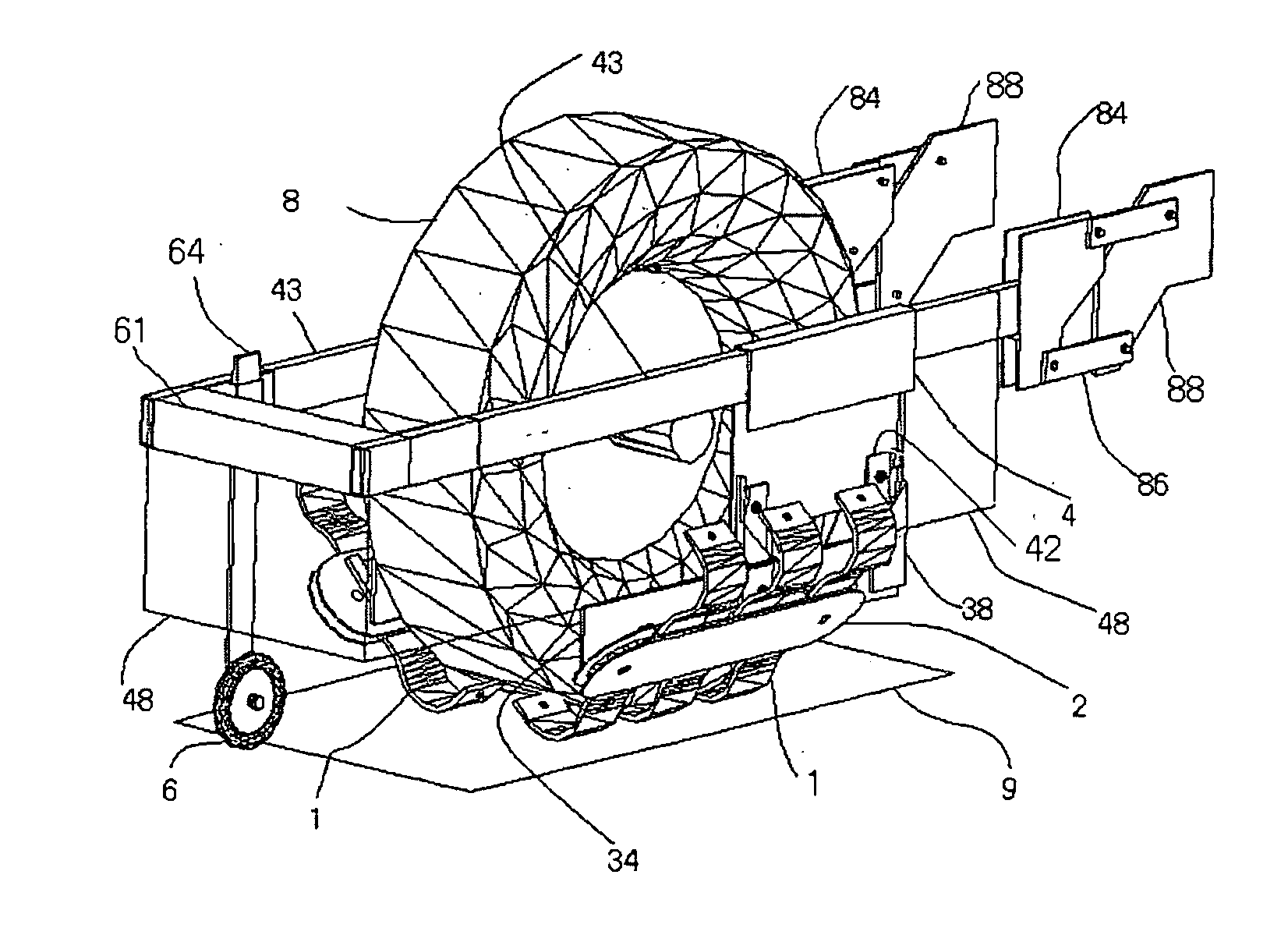
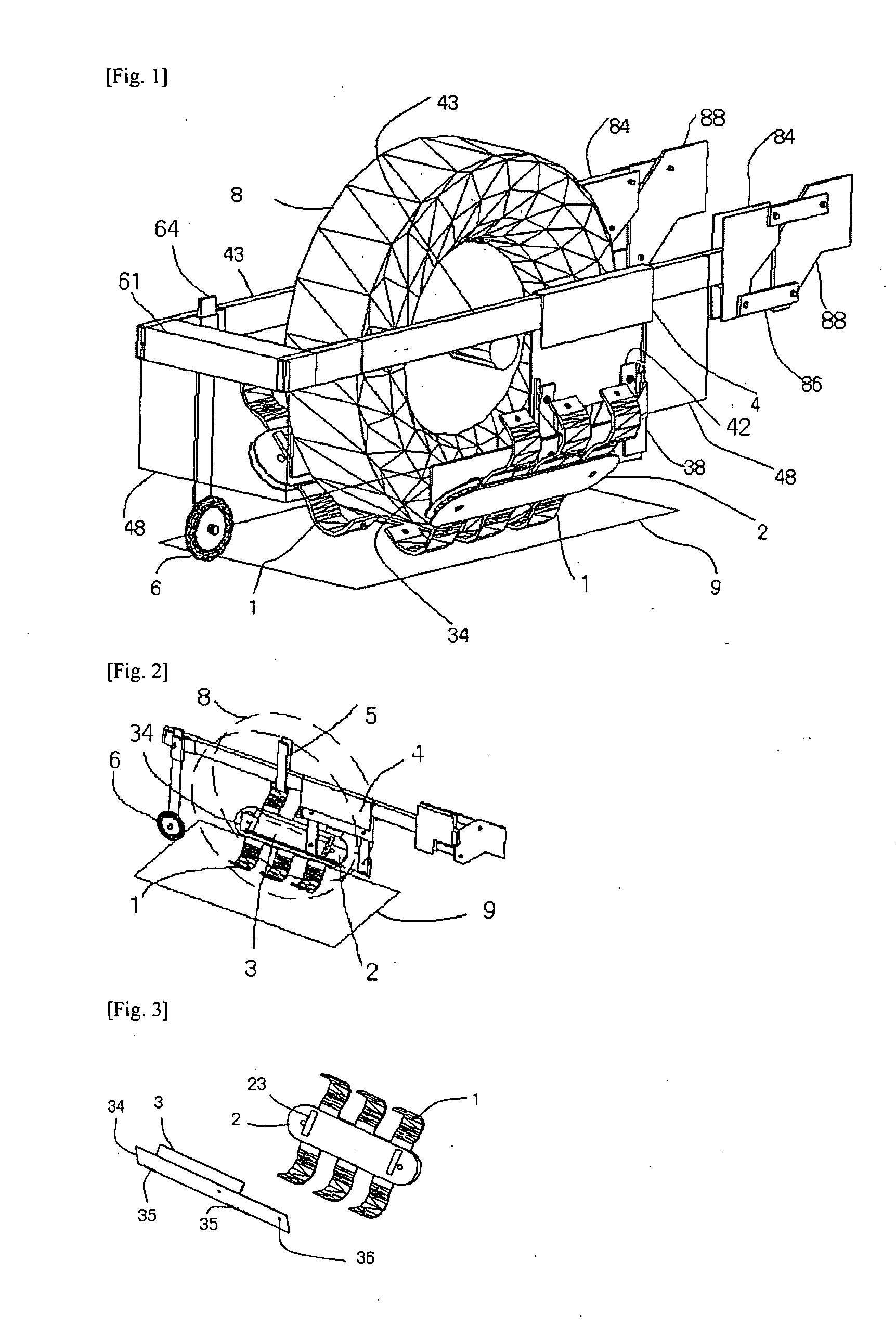
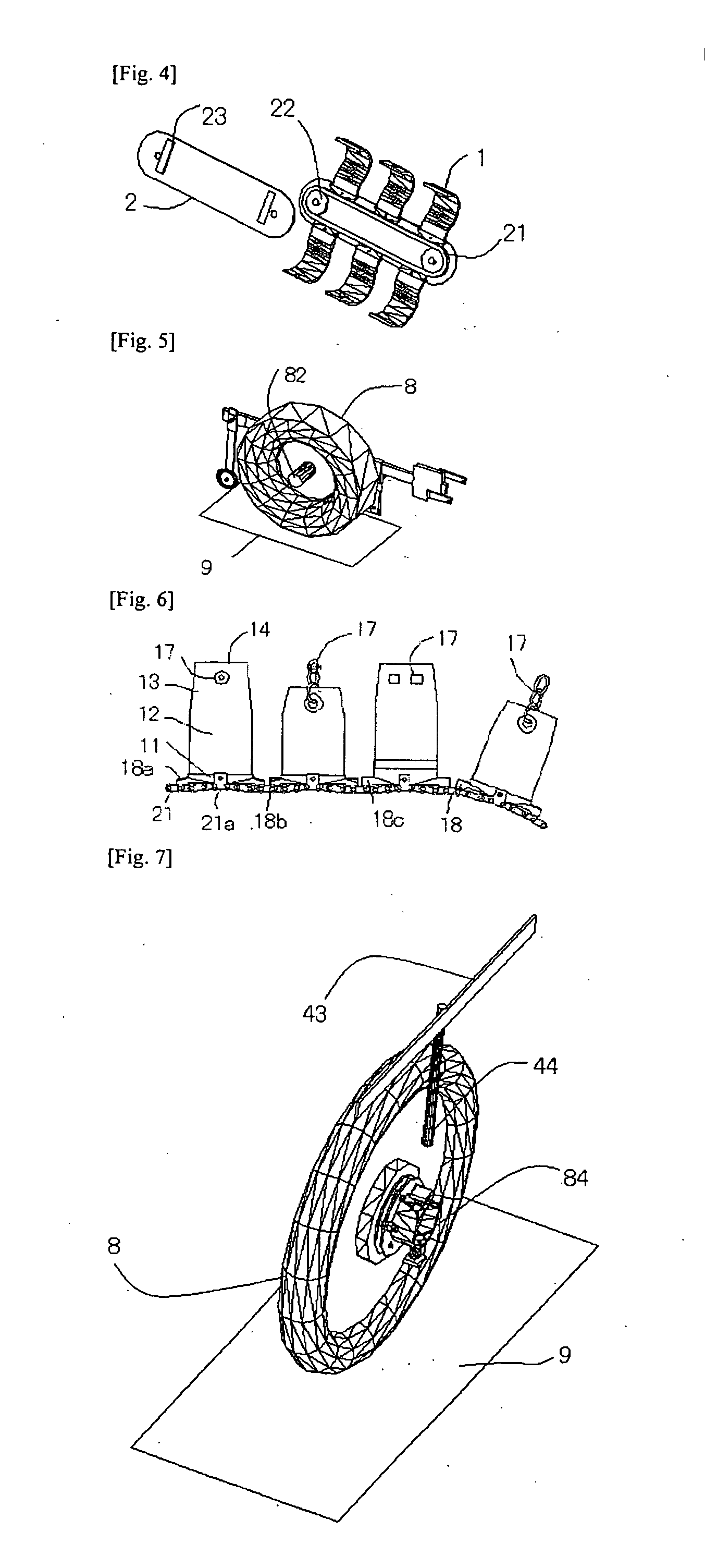
[0090]Referring to FIG. 1, a couple of the control units are set on both sides of the wheel 8. Each of these forms a hierarchical structure, including parts from the trodden part 14 via the adjusting part 4 to the positioning part 43 and has the installing equipment 88 fixed to the steel frame of a vehicle (a truck). Said installing equipment 88 supports a lifting equipment 86 which consists of swing arm(s) to lift or lower a linking part 84, into which the end of the positioning part 43 is inserted and fixed with a detachable mechanism such as a latch or a cotter. This control unit holds a sub unit, starting from said adjusting part4 which can adjust the position of the retainer 2 for a different vehicle. In addition the unit can slide toward the front in order to transfer the retainer 2 to the open space, where it is easy to replace the retainer 2 as well as trodden part 14. The buffering part 42, connected to the adjusting part 4, consists of two swing arms and supports, with rot...


PUM


Abstract

This invention is a control device to vary the contact conditions of the tread of a vehicle to improve driving functions, such as skid prevention, noise reduction, road surface protection or road marking, by the choice of the appropriate trodden tips in given road conditions. The trodden tips and connected parts are unified to make a unit which is attached or detached with a simple connection such as the insertion at a convenient position, which enables the device to function properly with a lowered safety factor, reducing the size only to avoid damages of the device and around.

Description

TECHNICAL FIELD[0001]The present invention relates to a device for varying the contact conditions between the ground surface and the tread of the wheeled vehicles by inserting the treading piece which is simple, light, small and durable, yet versatile.BACKGROUND ART[0002]Various inventions have improved the contact conditions of the tread since the invention of the wheel. In recent years, wheeled vehicles are being used more and more in winter so that demand has particularly increased for skid prevention on ice. Conventional means may be divided broadly into two categories:1) On the ground; this category consists of two types: One is a permanent type such as heating pavements with a drawback of high cost. Another is a temporary type such as a traction pad, or a so called “snow helper”, which is a ragged thin board, commonly used for emergencies in cold regions of Japan. The drawback is not only their limited length but it is troublesome work to place these on the ground.2) On vehicl...

Claims


Application Information

Patent Timeline
Patent Type & Authority Applications(United States)
IPC IPC(8): B60B39/00
CPCB60B39/00B60B15/00
Inventor INUZUKA, MASAO
Owner INUZUKA MASAO
Why Eureka
Try Eureka