Optical apparatus including an image stabilizing apparatus

an image stabilizing and optical technology, applied in the field of optical apparatuses, can solve the problems of deteriorating driving responsibility, affecting optical performance, and unable to perform precise image blur correction, so as to improve the position accuracy in the optical axis direction, not affect optical performance, and correct the tilt of the image stabilizing uni

Active Publication Date: 2011-01-20
CANON KK
View PDF10 Cites 48 Cited by
  • Summary
  • Abstract
  • Description
  • Claims
  • Application Information

AI Technical Summary

Benefits of technology

[0021]In addition, in the image stabilizing apparatus according to the present invention, the drive unit includes a yoke formed of a magnetic material magnetically coupled to a magnet, and is fixed integrally with the fixed member, and the yoke includes abutting portions in which the third rolling ball and at least two of the first rolling balls abut against the fixed member. As a result, the positional accuracy in the optical axis direction can be increased without increasing the number of components. Moreover, the biasing unit includes three biasing sub-units and the three biasing sub-units are arranged at the same position as a position of the second rolling balls and the third rolling ball in the rotating direction about the optical axis. Thus, the image stabilizing apparatus is allowed to have a compact configuration in the optical axis direction.
[0022]Further, the image stabilizing ap...

Problems solved by technology

Second, it is necessary to correct an optical axis change caused by the camera vibration through displacing the correction lens.
This is because, when rolling occurs besides movement in the pitch direction and the yaw direction, a position detecting unit detects a moving amount different from an actual blur correction amount to perform false correction based on a false signal such as so-called crosstalk, with the result that precise image blur correction cannot be performed.
Therefore, there is a problem in that sliding friction generated in the guide mechanism deteriorates driving responsibility during, in particular, micro driving of the correction lens.
Thus, the image sta...

Method used


Image

  • Optical apparatus including an image stabilizing apparatus
  • Optical apparatus including an image stabilizing apparatus
  • Optical apparatus including an image stabilizing apparatus

Examples


embodiment

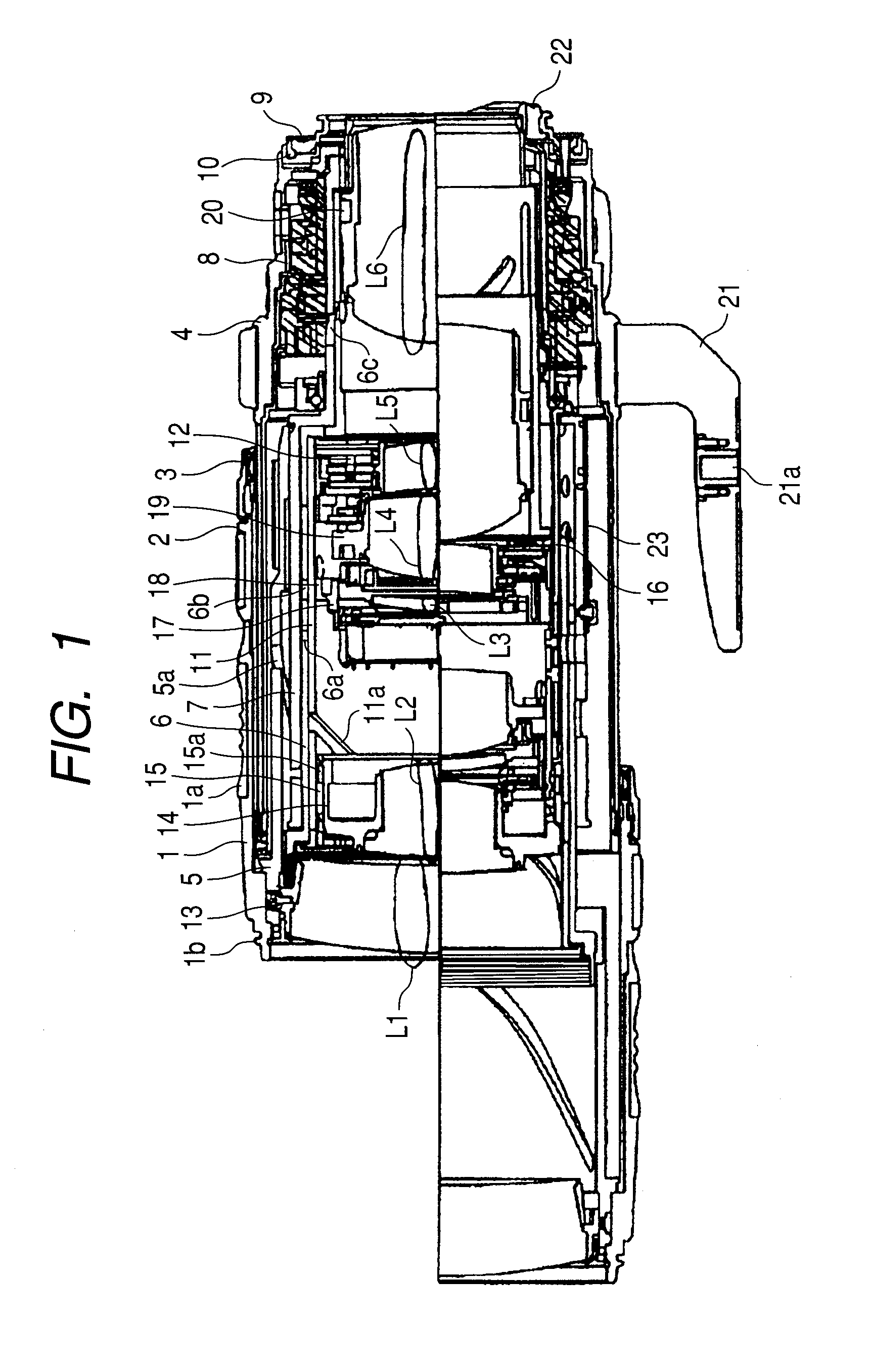
[0038]FIG. 1 illustrates a configuration of a lens apparatus as an optical apparatus according to the embodiment of the present invention. The lens apparatus is an interchangeable lens (zoom lens) for a single-lens reflex camera. An upper side with respect to a center line of FIG. 1 illustrates a configuration of the lens apparatus at a wide angle end, and a lower side with respect to the center line of FIG. 1 illustrates a configuration of the lens apparatus at a telephoto end. Note that, in the following description, an object side is referred to as a front side, and an image side is referred to as a back side.

[0039]An image pickup optical system includes a first lens unit L1 to a sixth lens unit L6. Through a translation operation of a zoom operation ring 1, the first lens unit L1 to the sixth lens unit L6 move in an optical axis direction, and change a focal length of the image pickup optical system. In order to facilitate the operation, a rubber ring 1a is attached onto an oute...


PUM


Abstract

An image stabilizer includes: an optical system movable in a plane perpendicular to an optical axis (“orthogonal plane”) and correcting image blur; a movable member holding the optical system and movable relative to a fixed member in an orthogonal plane; a guide guiding the movable member while preventing from rotating in an orthogonal plane; three first balls rollably interposed between the fixed and guide members; two second balls rollably interposed between the guide and movable members; one third ball rollably interposed between the fixed and movable members; a biasing unit biasing the movable member toward the fixed member; and a drive unit driving the movable member relative to the fixed member in two directions perpendicular to the optical axis, wherein in an orthogonal plane, two of the first balls are rollable only in first direction; the second balls are rollable only in second direction different from the first direction.

Description

BACKGROUND OF THE INVENTION[0001]1. Field of the Invention[0002]The present invention relates to an optical apparatus including an image stabilizing apparatus which detects vibration (shaking) generated in the optical apparatus or the like, and causes a lens (image stabilizing unit) to move in a direction perpendicular to an optical axis while detection of the vibration is used as information for image blur correction, to thereby correct an image blur.[0003]2. Description of the Related Art[0004]In a camera, nowadays, because operations such as exposure determination and focusing important for photographing are all automated, a risk that those unskilled in camera operation may fail in photographing has been greatly reduced. In addition, in recent years, studies have been conducted on a system which corrects an image blur caused by shaking applied to the camera. Accordingly, there are now almost no factors to cause photographers to fail in photographing.[0005]Here, the system that co...

Claims


Application Information

Patent Timeline
IPC IPC(8): G02B27/64
CPCG02B27/646
Inventor SATO, SHIGEKI
Owner CANON KK
Why Eureka
Try Eureka