
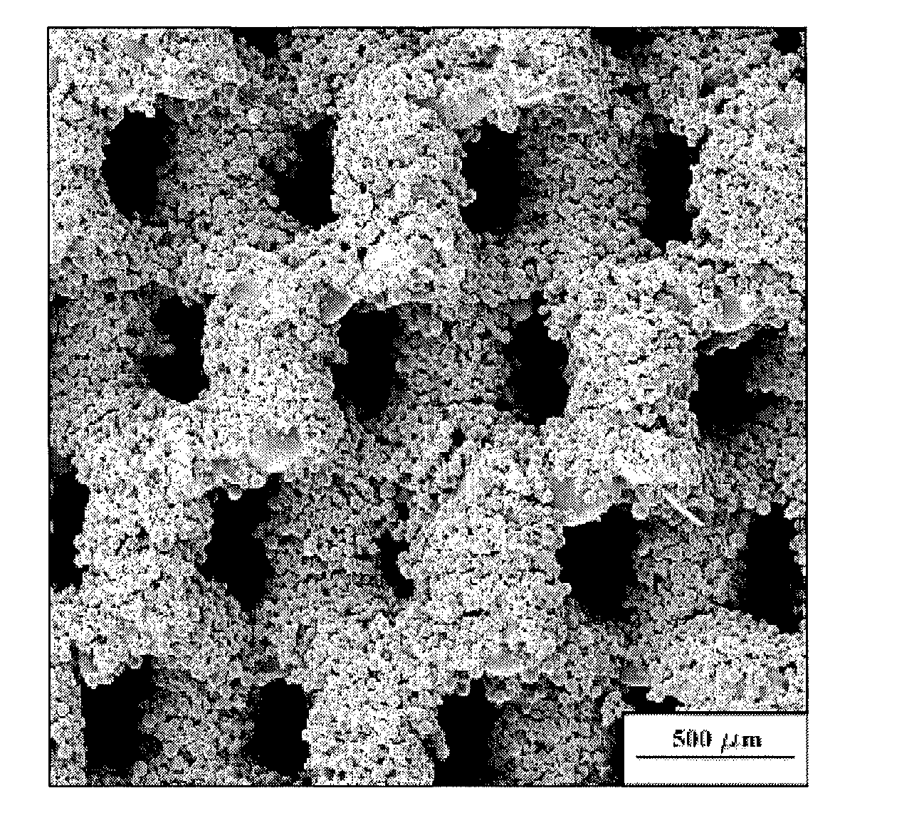
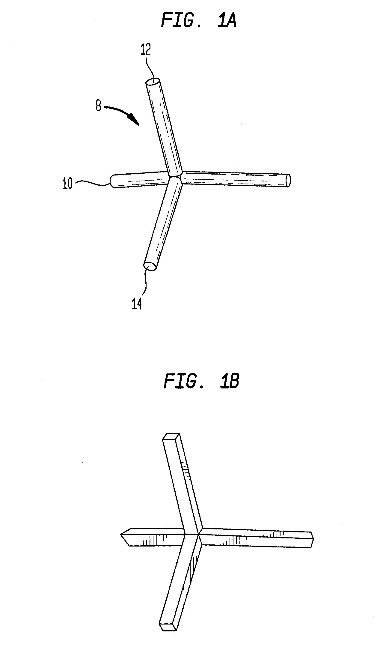
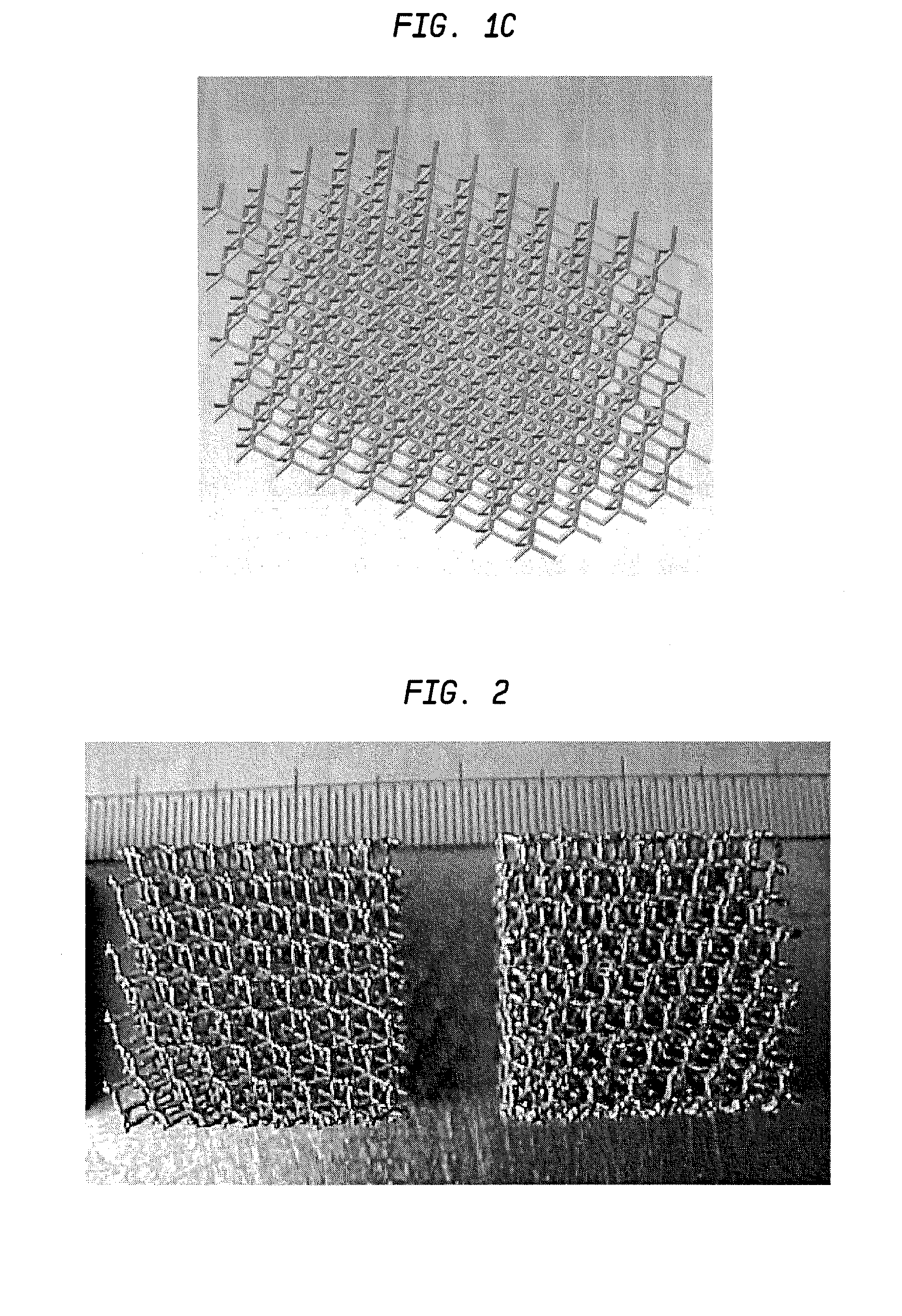
Laser-produced porous structure

a porous structure and laser-produced technology, applied in the field of porous surface or structure, can solve the problem that the field has not focused on reducing the density of three-dimensional structures

Active Publication Date: 2011-01-20
UNIV OF LIVERPOOL +1
View PDF101 Cites 202 Cited by
  • Summary
  • Abstract
  • Description
  • Claims
  • Application Information

AI Technical Summary

Benefits of technology

The present invention provides a method for creating structures and surfaces with interconnected pores, similar to medical implants. The method involves depositing layers of metal powder and scanning them with a laser beam to selectively melt and form portions of predetermined unit cells. The size and shape of the pores and porosity of the structure can be controlled. The method can be used to produce a three-dimensional porous tissue in-growth structure. The invention also includes a method for removing satellites and adjusting the length and cross-section of struts. The metal powder layers can be coated with unmelted metal particles.

Problems solved by technology

However, while the field of rapid prototyping has focused on increasing density of such three-dimensional structures, the field has not focused its attention on reducing the density of three-dimensional structures.

Method used


Image

  • Laser-produced porous structure
  • Laser-produced porous structure
  • Laser-produced porous structure

Examples


Embodiment Construction

[0074]This invention relates to a method of forming porous and partially porous metallic structures which are particularly but not exclusively applicable for use in hard or soft tissue interlock structures for medical implants and prosthesis. The method makes use of laser technology by employing a variety of scanning strategies. Typical metal and metal alloys employed include stainless steel, cobalt chromium alloys, titanium and its alloys, tantalum and niobium, all of which have been used in medical device applications. This invention can be used for such medical device applications where bone and soft tissue interlock with the component is required, or where a controlled structure is required to more closely match the mechanical properties of the device with surrounding tissue.

[0075]The intention of the present invention is to produce a three-dimensional structure using a laser remelting process, for example, for building structures utilizing unit cells with or without a solid bas...


PUM

PropertyMeasurementUnit
lengthaaaaaaaaaa
thicknessaaaaaaaaaa
poweraaaaaaaaaa

Abstract

The present invention disclosed a method of producing a three-dimensional porous tissue in-growth structure. The method includes the steps of depositing a first layer of metal powder and scanning the first layer of metal powder with a laser beam to form a portion of a plurality of predetermined unit cells. Depositing at least one additional layer of metal powder onto a previous layer and repeating the step of scanning a laser beam for at least one of the additional layers in order to continuing forming the predetermined unit cells. The method further includes continuing the depositing and scanning steps to form a medical implant.

Description

CROSS-REFERENCE TO RELATED APPLICATIONS[0001]This application is a continuation of U.S. application Ser. No. 11 / 027,421, filed on Dec. 30, 2004, the disclosure of which is incorporated herein by reference.BACKGROUND OF THE INVENTION[0002]The present invention relates to a porous surface or structure and a method for forming the same, which uses a directed energy beam to selectively remelt a powder to produce a part. The energy beam may include a laser beam, and an electron beam or the like. In particular, this invention relates to a computer-aided laser apparatus, which sequentially remelts a plurality of powder layers to form unit cells to build the designed part in a layer-by-layer fashion. The present application is particularly directed toward a method of forming a porous and partially porous metallic structure.[0003]The field of free-form fabrication has seen many important recent advances in the fabrication of articles directly from computer controlled databases. These advance...

Claims


Application Information

Patent Timeline
Patent Type & Authority Applications(United States)
IPC IPC(8): B22F3/11
CPCA61F2/2803A61F2/30767A61F2/30771A61F2/30907A61F2/3094A61F2/30965A61F2/36A61F2/3662A61F2/3859A61F2/389A61F2/4455A61F2002/30011A61F2002/30113A61F2002/30143A61F2002/30146A61F2002/30153A61F2002/30154A61F2002/30199A61F2002/30243A61F2002/30283A61F2002/30329A61F2002/30736A61F2002/30785A61F2002/30789A61F2002/30879A61F2002/30892A61F2002/30904A61F2002/30915A61F2002/3092A61F2002/30925A61F2002/30952A61F2002/30962A61F2002/30968A61F2002/3097A61F2002/30971A61F2002/3403A61F2002/3411A61F2002/3417A61F2002/3425A61F2002/3472A61F2002/3474A61F2002/4475A61F2220/0025A61F2230/0006A61F2230/0017A61F2230/0019A61F2230/0021A61F2230/0063A61F2230/0071A61F2250/0023A61F2310/00017A61F2310/00023A61F2310/00029A61F2310/00095A61F2310/00131A61F2310/00401A61F2310/00407A61F2310/00413A61F2310/00491A61F2310/00544A61L27/04A61L27/56B22F3/1055B22F3/1109B23K26/381C23C4/02C23C4/18C23C24/10C23C26/02B23K26/4005B23K26/401B23K26/4015B23K2203/04B23K2203/02B23K2203/08B23K26/4065B23K26/408B23K26/4095B23K2203/14B23K26/382B23K26/40B23K2103/18B23K2103/26B23K2103/50B23K2101/35B23K2103/02B23K2103/05B23K2103/08B23K2103/14B23K2103/52B33Y10/00B33Y80/00A61F2240/001A61F2002/3028A61F2002/30593A61F2002/30594A61F2002/305Y02P10/25B22F10/28B22F10/80B22F10/38B22F12/52B22F12/43B22F10/36B22F10/20B23K26/402B23K26/082B23K26/342
Inventor JONES, ERICSUTCLIFFE, CHRISTOPHER J.STAMP, ROBIN
Owner UNIV OF LIVERPOOL
Learn More