Hydrogen generation apparatus, fuel cell system and method of shutting down hydrogen generation apparatus

Active Publication Date: 2011-01-20
PANASONIC CORP
View PDF10 Cites 14 Cited by
  • Summary
  • Abstract
  • Description
  • Claims
  • Application Information

AI Technical Summary

Benefits of technology

[0042]According to the present disclosure, a hydrogen generation apparatus, a fuel cell system and a method of shutting down the hyd

Problems solved by technology

However, no general infrastructure for hydrogen gas or a gas containing hydrogen for fuel at power generation has been developed.
However, it is not easy to keep an inert gas prepared at all times in the case where the apparatus is installed in a hom

Method used


Image

  • Hydrogen generation apparatus, fuel cell system and method of shutting down hydrogen generation apparatus
  • Hydrogen generation apparatus, fuel cell system and method of shutting down hydrogen generation apparatus
  • Hydrogen generation apparatus, fuel cell system and method of shutting down hydrogen generation apparatus

Examples


embodiment 1

[0075]A hydrogen generation apparatus and the configuration of a fuel cell system having the hydrogen generation apparatus in Embodiment 1 of the present disclosure will first be described.

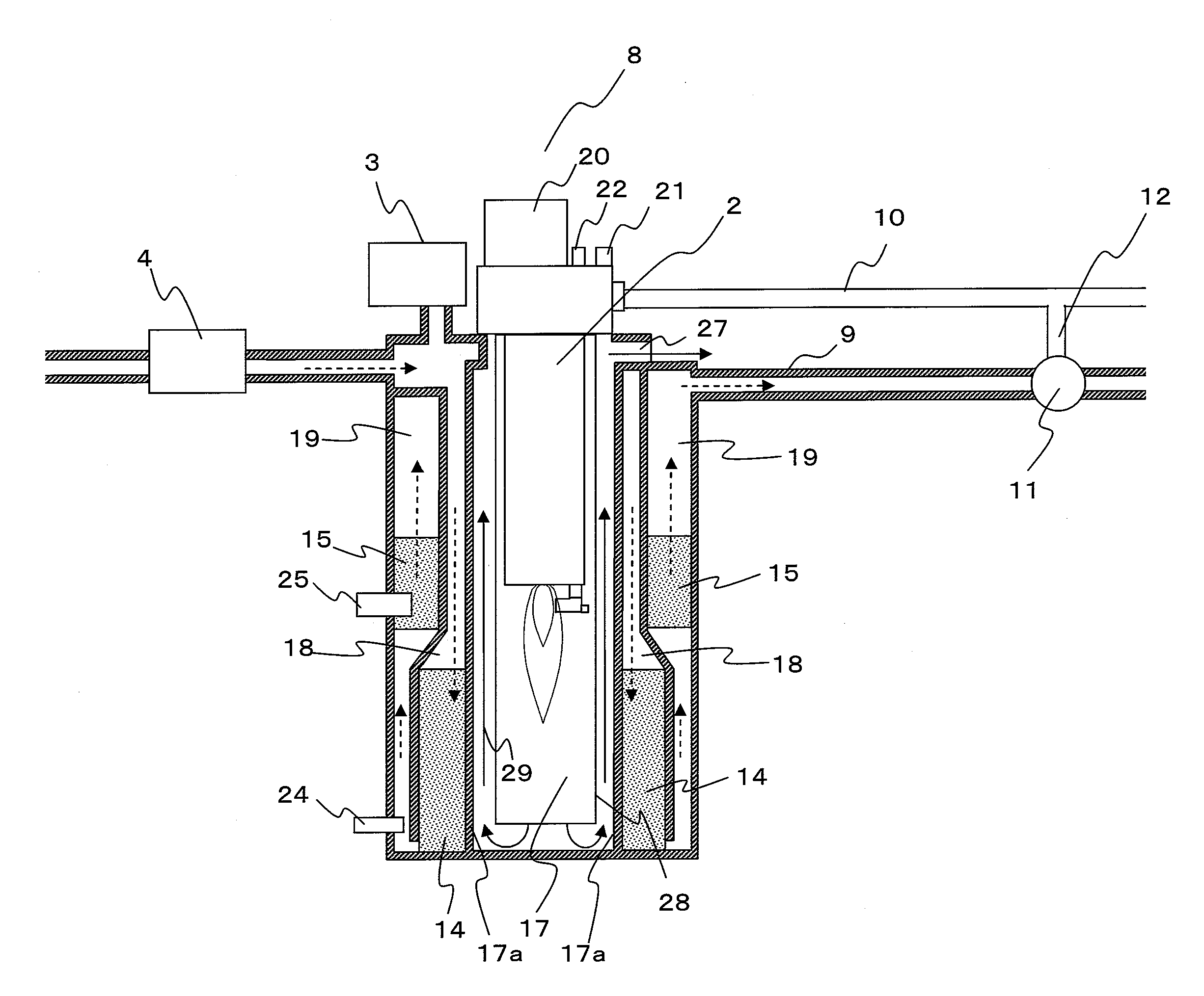
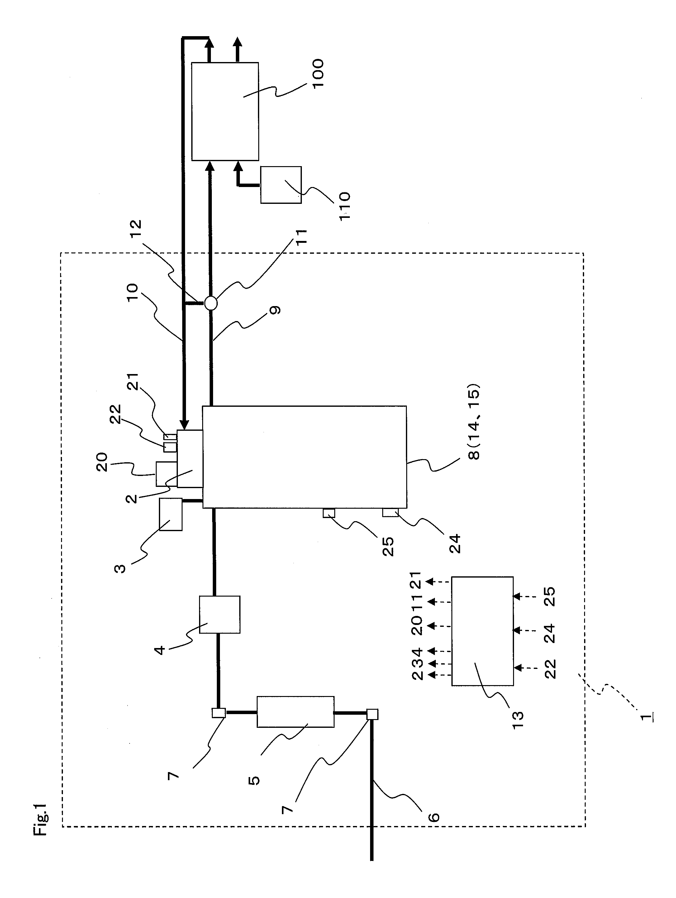
[0076]FIG. 1 is a configuration diagram of a hydrogen generation apparatus and a fuel cell system having the hydrogen generation apparatus in Embodiment 1 of the present disclosure. The fuel cell system in the present embodiment has a hydrogen generation apparatus 1 and a fuel cell 100. The hydrogen generation apparatus 1 is an apparatus which generates a gas containing hydrogen mainly by causing progress in reforming reaction between water vapor and a raw material containing an organic compound such as hydrocarbon constituted at least of carbon and hydrogen, e.g., city gas containing methane as a main constituent, natural gas or LPG. The fuel cell 100 is an apparatus which generates electric power by using as an anode gas the gas containing hydrogen supplied from the hydrogen generation apparatus...

example 1

[0118]Functions to shut down the hydrogen generation apparatus 1 were performed by preparing a program with the temperature T1 set to 320° C., the first reference temperature T2 and the second reference temperature T4 set to 120° C. and the reference temperature T3 set to 400° C. in the control flow of the shutdown method for the hydrogen generation apparatus 1 in FIG. 3. The rate of supply of air by the first air supplier 20 was set to 5 NL / min.

[0119]FIG. 5 is a diagram showing a graph of changes in the detected temperature TK and the detected temperature TH with respect to time. The first air supplier 20 was made to function from a time 20 minutes after shutdown to a time 72 minutes after shutdown on the basis of the above-described flow from step 2 to step 7. When the detected temperature TK became equal to 320° C., the detected temperature TH was 99° C. Even after repeating startup and shutdown 100 times, no reductions in strength and no reductions in activity of the catalysts w...

embodiment 2

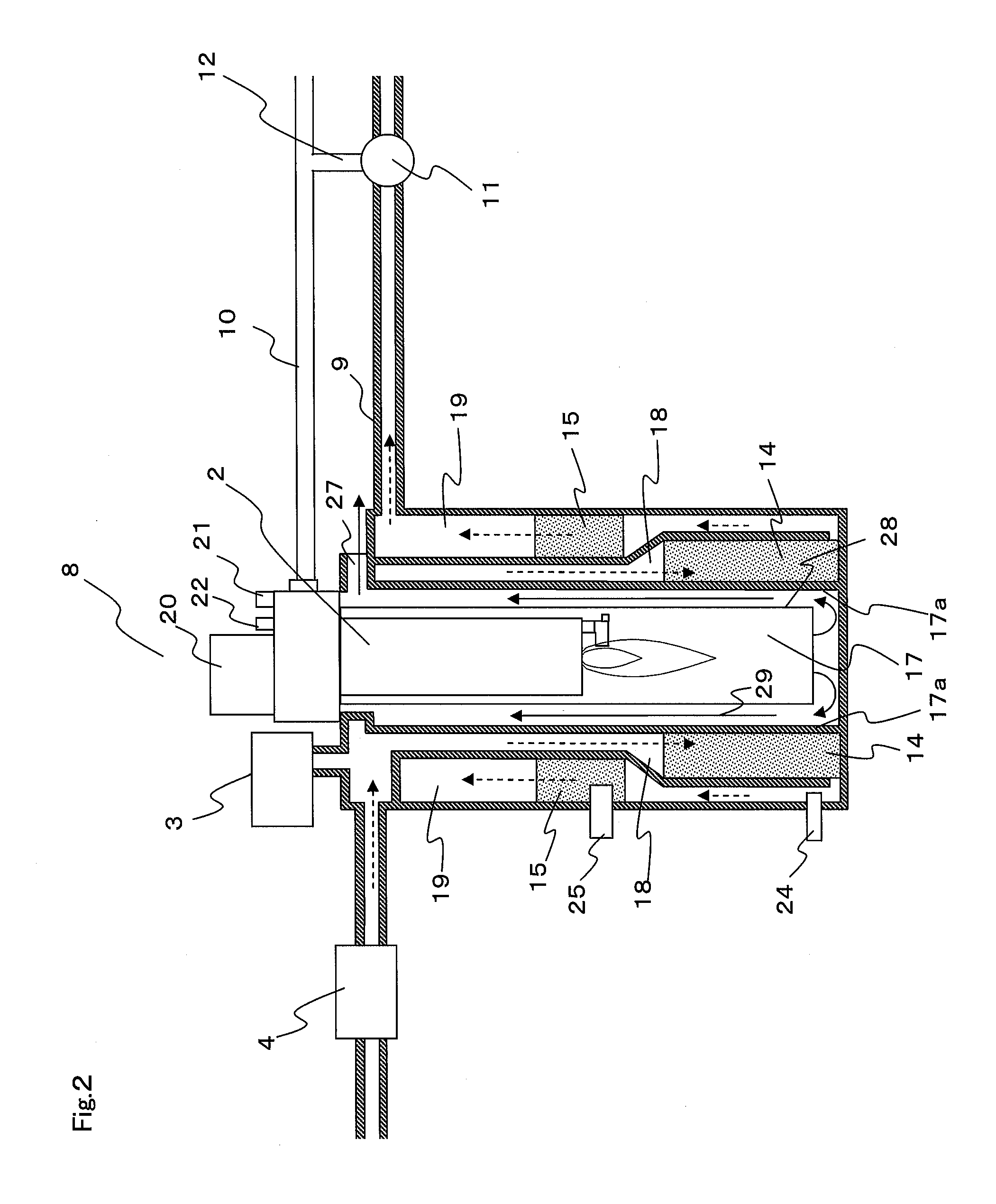
[0137]A hydrogen generation apparatus and a fuel cell system having the hydrogen generation apparatus in Embodiment 2 of the present disclosure will be described below. The hydrogen generation apparatus and the fuel cell system having the hydrogen generation apparatus in the present Embodiment 2 have basically the same configuration as that in Embodiment 1. However, the configuration in the present Embodiment 2 differs from that in Embodiment 1 in that a first heater for heating the converting device 15 is provided in the hydrogen generation apparatus. Description will therefore be made mainly of this point of difference. In the present Embodiment 2, the same components as those in Embodiment 1 are indicated by the same reference characters.

[0138]FIG. 7 is a sectional configuration diagram of a hydrogen generator 41 of a hydrogen generation apparatus 40 in the present Embodiment 2. In contrast to the hydrogen generator 8 in Embodiment 1, the hydrogen generator 41 has a first heater ...


PUM


Abstract

A method of shutting down a hydrogen generation apparatus for limiting degradation in a catalyst due to dew condensation at the time of shutdown is provided. The method of shutting down the hydrogen generation apparatus comprising, a combustor which supplies heat necessary to a reforming device, a first air supplier which supplies air to the combustor, a combustion exhaust gas path formed such that the combustion exhaust gas produced in the combustor makes heat exchange with the reforming device and then with a CO reducing device, and a controller which operates the first air supplier so that the temperature of the gas in the CO reducing device does not become equal to or lower than a dew point after shutdown of the combustion operation of the combustor and before a start of a purging operation to purge the interiors of the reforming device and the CO reducing device with a replacement gas.

Description

CROSS-REFERENCE TO RELATED APPLICATIONS[0001]This application is a U.S. national phase application of PCT International Patent Application No. PCT / JP2010 / 000256 filed Jan. 19, 2010, claiming the benefit of priority of Japanese Patent Application No. 2009-009119 filed Jan. 19, 2009, all of which are incorporated by reference herein in their entirety.TECHNICAL FIELD[0002]The present disclosure relates to a hydrogen generation apparatus which generates a gas containing hydrogen by reforming reaction between a raw material and water, a fuel cell system and a method of shutting down the hydrogen generation apparatus.BACKGROUND ART[0003]Development of fuel cells capable of high-efficiency power generation even in a small unit and using hydrogen gas or a gas containing hydrogen as fuel is being pursued to develop the fuel cells as a power generation system for distributed energy supply sources. However, no general infrastructure for hydrogen gas or a gas containing hydrogen for fuel at pow...

Claims


Application Information

Patent Timeline
IPC IPC(8): H01M8/06C01B3/02
CPCY02E60/50B01J2219/00238C01B2203/0445H01M8/04223C01B2203/066B01J2219/00231C01B3/382H01M8/0618B01J2208/00646C01B2203/1695C01B2203/1619C01B2203/0811C01B2203/047C01B2203/0822B01J2208/00504C01B2203/0283C01B2203/0244C01B2203/1604B01J2208/00637B01J2219/002C01B3/384C01B2203/0827H01M8/0668C01B2203/0233C01B2203/1609C01B2203/044B01J2219/00236B01J2208/00061B01J8/0465Y02P20/10H01M8/04303H01M8/04302
Inventor KANI, YUKIMUNEFUJIHARA, SEIJI
Owner PANASONIC CORP
Why Eureka
Try Eureka