Transapical delivery system for heart valves

Active Publication Date: 2011-01-20
EDWARDS LIFESCIENCES CORP
View PDF99 Cites 419 Cited by
  • Summary
  • Abstract
  • Description
  • Claims
  • Application Information

AI Technical Summary

Benefits of technology

[0010]Preferred embodiments of the present invention provide a heart valve delivery system for delivery of a prosthetic (i.e., replacement) heart valve to a native

Problems solved by technology

Valve replacement surgery is a highly invasive operation with significant concomitant risks include bleeding, infection, stroke, heart attack, arrhythmia, renal failure, adverse reactions t

Method used


Image

  • Transapical delivery system for heart valves
  • Transapical delivery system for heart valves
  • Transapical delivery system for heart valves

Examples


Embodiment Construction

[0043]The heart is a hollow muscular organ of a somewhat conical form; it lies between the lungs in the middle mediastinum and is enclosed in the pericardium. The heart rests obliquely in the chest behind the body of the sternum and adjoining parts of the rib cartilages, and projects farther into the left than into the right half of the thoracic cavity so that about one-third is situated on the right and two-thirds on the left of the median plane. The heart is subdivided by septa into right and left halves, and a constriction subdivides each half of the organ into two cavities, the upper cavity being called the atrium, the lower the ventricle. The heart therefore consists of four chambers; the right and left atria, and right and left ventricles.

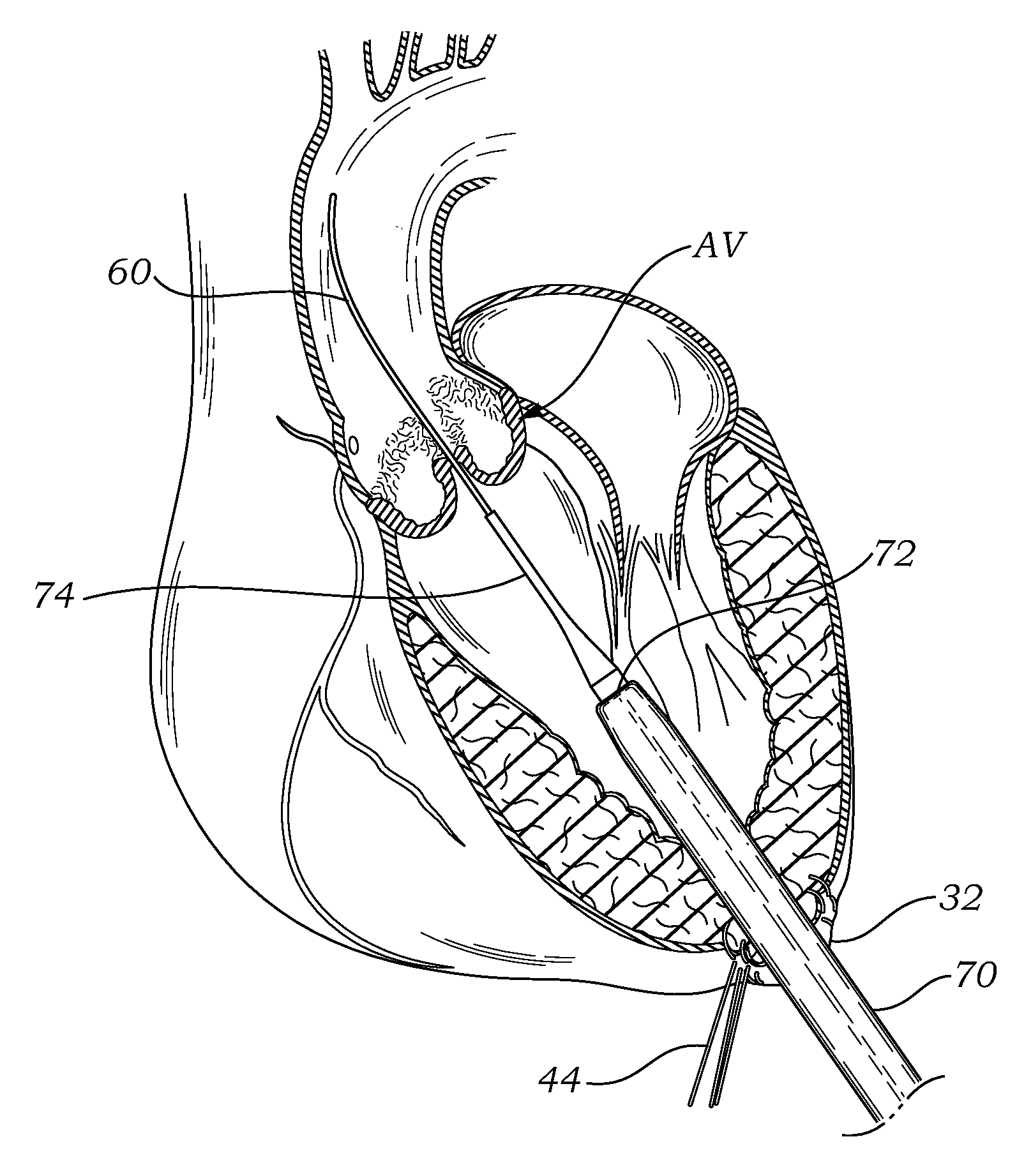
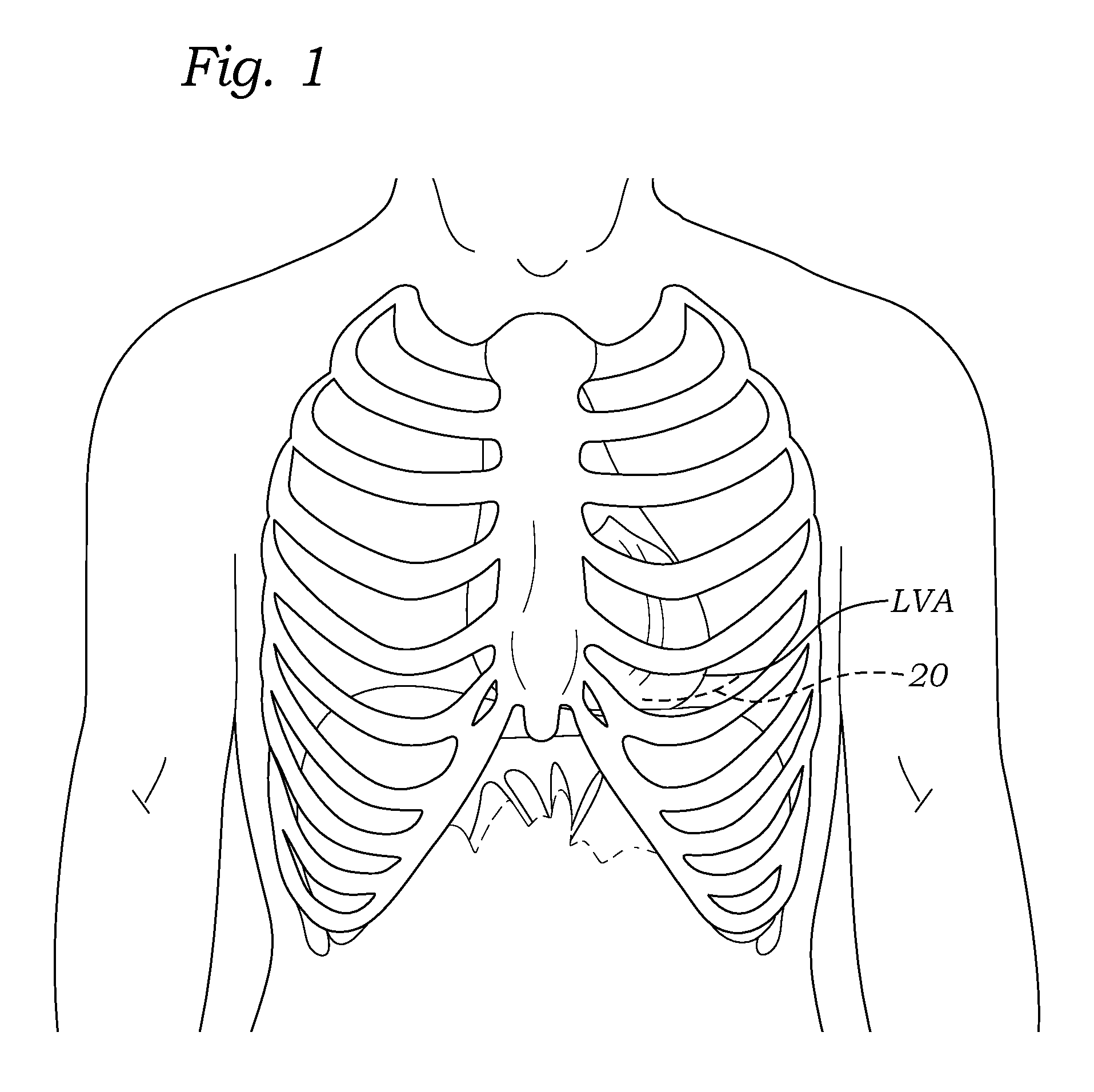
[0044]As seen in FIG. 1, the left ventricular apex LVA is directed downward, forward, and to the left (from the perspective of the patient). The apex typically lies behind the fifth left intercostal space (or between the fourth and fifth), 8 ...


PUM


Abstract

A delivery system and method for delivering a prosthetic heart valve to the aortic valve annulus. The system includes a delivery catheter having a steering mechanism thereon for delivering a balloon-expandable prosthetic heart valve to the aortic annulus in an antegrade fashion through an introducer passing into the left ventricle through its apex. The introducer may have a more floppy distal section than a proximal section to reduce trauma to the heart wall while preserving good operating field stability. The delivery catheter includes a deflecting segment just proximal to a distal balloon to facilitate positioning of the prosthetic heart valve in the proper orientation within the aortic annulus. A trigger in a catheter handle may be coupled to a deflection wire that actuates the deflecting segment, while a slider in the handle controls retraction of a valve pusher. The prosthetic heart valve may be installed over the existing calcified leaflets, and a pre-dilation valvuloplasty procedure may also be utilized.

Description

RELATED APPLICATIONS[0001]The present application claims priority under 35 U.S.C. §119(e) to U.S. provisional application No. 61 / 225,510 filed Jul. 14, 2009.FIELD OF THE INVENTION[0002]The present invention relates to methods and systems used to deliver a prosthetic valve to a heart. More specifically, the present invention relates to methods and apparatus for surgically replacing a heart valve without opening the chest cavity and with or without placing the patient on bypass, the latter being termed “off-pump.”BACKGROUND OF THE INVENTION[0003]Heart valve replacement may be indicated when there is a narrowing of the native heart valve, commonly referred to as stenosis, or when the native valve leaks or regurgitates, such as when the leaflets are calcified. When replacing the valve, the native valve may be excised and replaced with either a biologic or a mechanical valve. Mechanical valves require lifelong anticoagulant medication to prevent blood clot formation, and clicking of the ...

Claims


Application Information

Patent Timeline
IPC IPC(8): A61F2/24A61F2/958
CPCA61F2/2418A61F2/2433A61F2220/005A61M25/0147A61F2220/0016A61M25/0136A61F2/2412A61M25/0141A61M25/0144A61F2/243A61M25/0138A61M2025/015A61M25/0133A61F2/2427
Inventor JIMENEZ, TEODORO S.LEE, WALTERDEHDASHTIAN, MARKYEE, KRISTOPHER
Owner EDWARDS LIFESCIENCES CORP
Why Eureka
Try Eureka